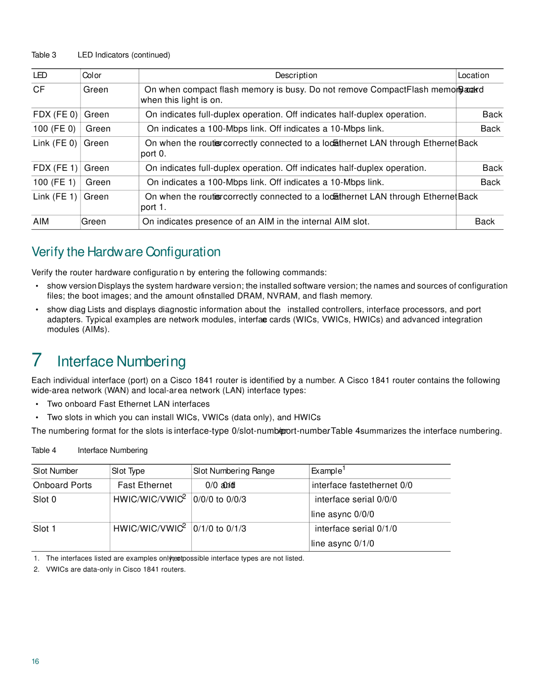
Table 3 | LED Indicators (continued) |
| ||
|
|
|
|
|
LED |
| Color | Description | Location |
|
|
|
|
|
CF |
| Green | On when compact flash memory is busy. Do not remove CompactFlash memory card | Back |
|
|
| when this light is on. |
|
|
|
|
|
|
FDX (FE 0) |
| Green | On indicates | Back |
|
|
|
|
|
100 (FE 0) |
| Green | On indicates a | Back |
|
|
|
|
|
Link (FE 0) |
| Green | On when the router is correctly connected to a local Ethernet LAN through Ethernet | Back |
|
|
| port 0. |
|
|
|
|
|
|
FDX (FE 1) |
| Green | On indicates | Back |
|
|
|
|
|
100 (FE 1) |
| Green | On indicates a | Back |
|
|
|
|
|
Link (FE 1) |
| Green | On when the router is correctly connected to a local Ethernet LAN through Ethernet | Back |
|
|
| port 1. |
|
|
|
|
|
|
AIM |
| Green | On indicates presence of an AIM in the internal AIM slot. | Back |
|
|
|
|
|
Verify the Hardware Configuration
Verify the router hardware configuration by entering the following commands:
•show
•show
7Interface Numbering
Each individual interface (port) on a Cisco 1841 router is identified by a number. A Cisco 1841 router contains the following
•Two onboard Fast Ethernet LAN interfaces
•Two slots in which you can install WICs, VWICs (data only), and HWICs
The numbering format for the slots is
Table 4 | Interface Numbering |
|
| |
|
|
|
|
|
Slot Number |
| Slot Type | Slot Numbering Range | Example1 |
Onboard Ports | Fast Ethernet | 0/0 and 0/1 | interface fastethernet 0/0 | |
|
|
|
|
|
Slot 0 |
| HWIC/WIC/VWIC2 | 0/0/0 to 0/0/3 | interface serial 0/0/0 |
|
|
|
| line async 0/0/0 |
|
|
|
|
|
Slot 1 |
| HWIC/WIC/VWIC2 | 0/1/0 to 0/1/3 | interface serial 0/1/0 |
|
|
|
| line async 0/1/0 |
|
|
|
|
|
1.The interfaces listed are examples only; other possible interface types are not listed.
2.VWICs are
16
