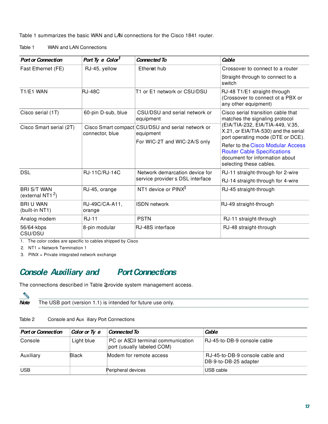
Table 1 summarizes the basic WAN and LAN connections for the Cisco 1841 router.
Table 1 | WAN and LAN Connections |
|
| ||
|
|
|
| ||
Port or Connection | Port Type, Color1 | Connected To: | Cable | ||
Fast Ethernet (FE) | Ethernet hub | Crossover to connect to a router | |||
|
|
|
| ||
|
|
|
| switch | |
|
|
|
| ||
T1/E1 WAN | T1 or E1 network or CSU/DSU | ||||
|
|
|
| (Crossover to connect ot a PBX or | |
|
|
|
| any other equipment) | |
|
|
|
| ||
Cisco serial (1T) | CSU/DSU and serial network or | Cisco serial transition cable that | |||
|
|
| equipment | matches the signaling protocol | |
|
|
|
| ||
Cisco Smart serial (2T) | Cisco Smart compact | CSU/DSU and serial network or | |||
X.21, or | |||||
|
| connector, blue | equipment | ||
|
| port operating mode (DTE or DCE). | |||
|
|
| For | ||
|
|
| Refer to the Cisco Modular Access | ||
|
|
|
| ||
|
|
|
| Router Cable Specifications | |
|
|
|
| document for information about | |
|
|
|
| selecting these cables. | |
|
|
|
|
| |
DSL |
| Network demarcation device for | |||
|
|
| service provider’s DSL interface | ||
|
|
|
| ||
|
|
|
| ||
BRI S/T WAN | NT1 device or PINX3 | ||||
(external NT12) |
|
|
| ||
BRI U WAN | ISDN network | ||||
orange |
|
| |||
|
|
|
| ||
Analog modem | PSTN | ||||
|
|
|
|
| |
| |||||
CSU/DSU |
|
|
|
| |
|
|
|
|
| |
1.The color codes are specific to cables shipped by Cisco
2.NT1 = Network Termination 1
3.PINX = Private integrated network exchange
Console, Auxiliary, and USB Port Connections
The connections described in Table 2 provide system management access.
Note The USB port (version 1.1) is intended for future use only.
Table 2 | Console and Auxiliary Port Connections |
| ||
|
|
|
| |
Port or Connection | Color or Type | Connected To: | Cable | |
|
|
|
|
|
Console |
| Light blue | PC or ASCII terminal communication | |
|
|
| port (usually labeled COM) |
|
|
|
|
|
|
Auxiliary |
| Black | Modem for remote access | |
|
|
|
| |
|
|
|
|
|
USB |
| — | Peripheral devices | USB cable |
|
|
|
|
|
13