TROUBLE SHOOTING
Product discharged from air exhaust.
SCheck for diaphragm rupture.
SCheck tightness of (6) diaphragm nut.
Air Bubbles in Product Discharge.
SCheck connections of suction plumbing. S Check band clamps on intake manifold.
S Check “O” rings between intake manifold and fluid caps. S Check tightness of (6) diaphragm nut.
Pump blows air out main exhaust when stalled on either stroke.
SCheck “U” cups on (111) spool in major valve.
SCheck (141) valve plate and (140) insert for wear.
SCheck (103) sleeve and (2) “O” ring on diaphragm connecting rod. S Check (119) “O” rings on (118) piston for wear.
Low output volume.
SCheck air supply.
SCheck for plugged outlet hose.
SFor the pump to prime itself, it must be mounted in the vertical posi-
tion so that the balls will check by gravity.
SCheck for pump cavitation
SCheck all joints on intake manifolds and suction connections. These must be airtight.
SCheck for sticking or improperly seating check valves.
SIf pump cycles at a high rate or runs erratically, check (119) piston “O” rings for wear.
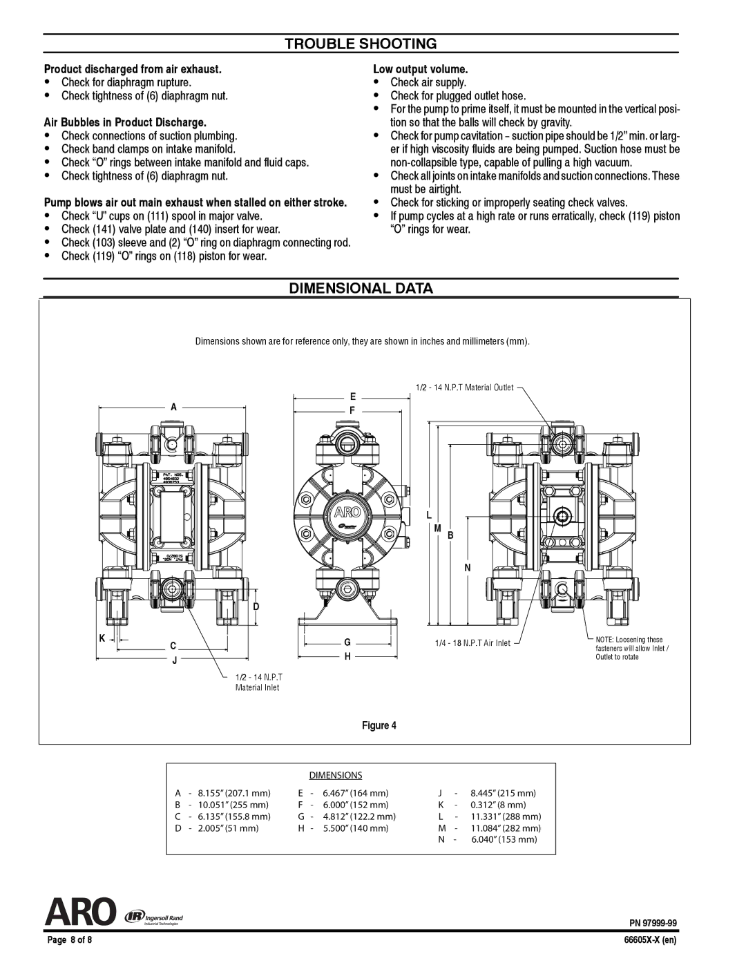
DIMENSIONAL DATA
Dimensions shown are for reference only, they are shown in inches and millimeters (mm).
A
D
E F
1/2 - 14 N.P.T Material Outlet
L
M B
N
K
C
J
1/2 - 14 N.P.T Material Inlet
G |
|
| 1/4 - 18 N.P.T Air Inlet | ||
| |||||
| |||||
H |
|
|
| ||
|
|
| |||
NOTE: Loosening these fasteners will allow Inlet / Outlet to rotate
Figure 4
|
|
|
| DIMENSIONS |
|
|
| |
A | - | 8.155” (207.1 mm) | E | - | 6.467” (164 mm) | J | - | 8.445” (215 mm) |
B | - | 10.051” (255 mm) | F | - | 6.000” (152 mm) | K | - | 0.312” (8 mm) |
C | - | 6.135” (155.8 mm) | G | - | 4.812” (122.2 mm) | L | - | 11.331” (288 mm) |
D | - | 2.005” (51 mm) | H | - | 5.500” (140 mm) | M | - | 11.084” (282 mm) |
|
|
|
|
|
| N | - | 6.040” (153 mm) |
|
|
|
|
|
|
|
|
|
| PN |
Page 8 of 8 |
