PARTS LIST /
nIndicates parts included in 637141 Air Section Repair Kit.
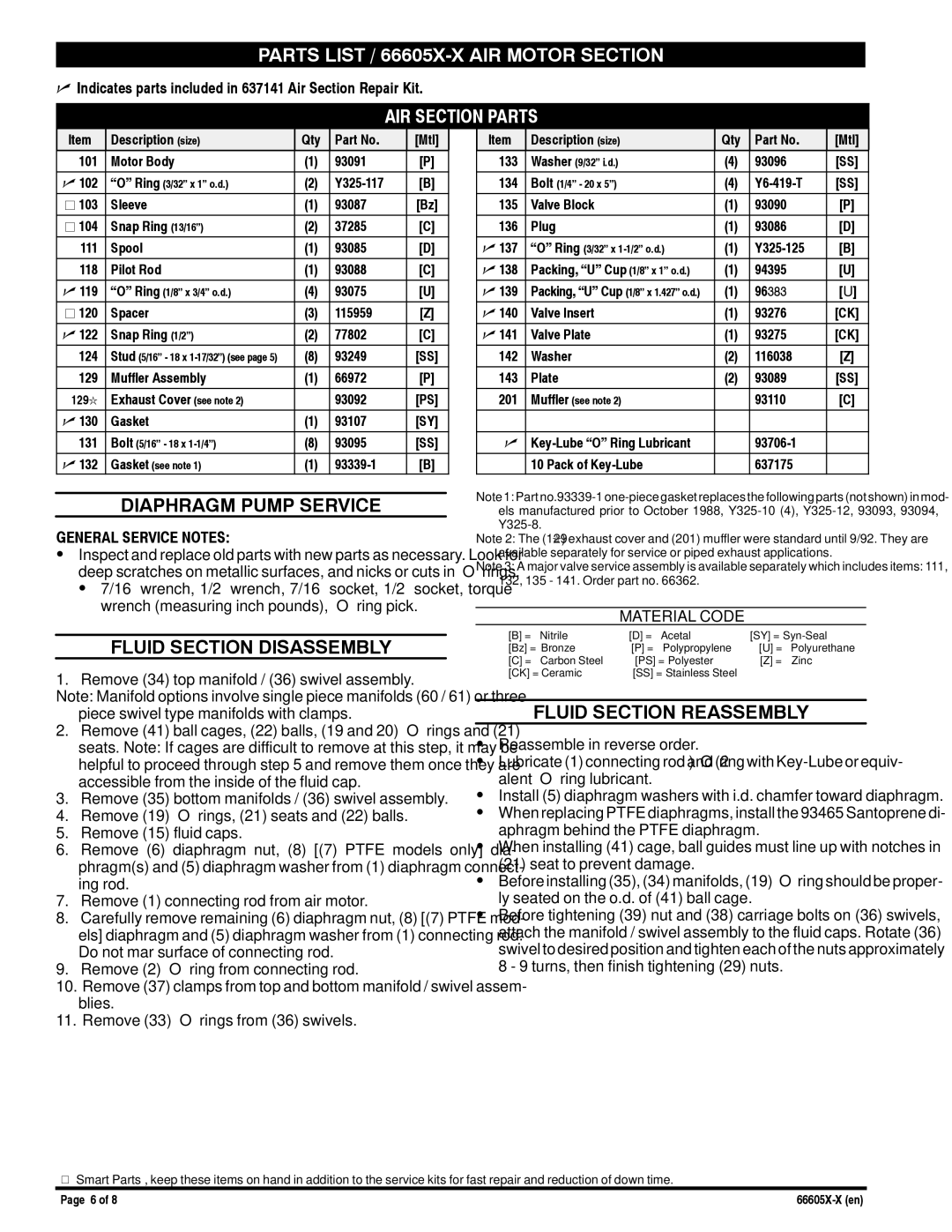
AIR SECTION PARTS
Item | Description (size) | Qty | Part No. | [Mtl] |
101 | Motor Body | (1) | 93091 | [P] |
|
|
|
|
|
n 102 | “O” Ring (3/32” x 1” o.d.) | (2) | [B] | |
j 103 | Sleeve | (1) | 93087 | [Bz] |
|
|
|
|
|
j 104 | Snap Ring (13/16”) | (2) | 37285 | [C] |
|
|
|
|
|
111 | Spool | (1) | 93085 | [D] |
118 | Pilot Rod | (1) | 93088 | [C] |
|
|
|
|
|
n 119 | “O” Ring (1/8” x 3/4” o.d.) | (4) | 93075 | [U] |
j 120 | Spacer | (3) | 115959 | [Z] |
|
|
|
|
|
n 122 | Snap Ring (1/2”) | (2) | 77802 | [C] |
124 | Stud (5/16” - 18 x | (8) | 93249 | [SS] |
|
|
|
|
|
129 | Muffler Assembly | (1) | 66972 | [P] |
129l | Exhaust Cover (see note 2) |
| 93092 | [PS] |
|
|
|
|
|
n 130 | Gasket | (1) | 93107 | [SY] |
|
|
|
|
|
131 | Bolt (5/16” - 18 x | (8) | 93095 | [SS] |
n 132 | Gasket (see note 1) | (1) | [B] |
DIAPHRAGM PUMP SERVICE
GENERAL SERVICE NOTES:
SInspect and replace old parts with new parts as necessary. Look for deep scratches on metallic surfaces, and nicks or cuts in “O” rings. S 7/16” wrench, 1/2” wrench, 7/16” socket, 1/2” socket, torque
wrench (measuring inch pounds), “O” ring pick.
FLUID SECTION DISASSEMBLY
1. Remove (34) top manifold / (36) swivel assembly.
Note: Manifold options involve single piece manifolds (60 / 61) or three piece swivel type manifolds with clamps.
2.Remove (41) ball cages, (22) balls, (19 and 20) “O” rings and (21) seats. Note: If cages are difficult to remove at this step, it may be helpful to proceed through step 5 and remove them once they are accessible from the inside of the fluid cap.
3.Remove (35) bottom manifolds / (36) swivel assembly.
4.Remove (19) “O” rings, (21) seats and (22) balls.
5.Remove (15) fluid caps.
6.Remove (6) diaphragm nut, (8) [(7) PTFE models only] dia- phragm(s) and (5) diaphragm washer from (1) diaphragm connect- ing rod.
7.Remove (1) connecting rod from air motor.
8.Carefully remove remaining (6) diaphragm nut, (8) [(7) PTFE mod- els] diaphragm and (5) diaphragm washer from (1) connecting rod. Do not mar surface of connecting rod.
9.Remove (2) “O” ring from connecting rod.
10.Remove (37) clamps from top and bottom manifold / swivel assem- blies.
11.Remove (33) “O” rings from (36) swivels.
Item | Description (size) | Qty | Part No. | [Mtl] |
133 | Washer (9/32” i.d.) | (4) | 93096 | [SS] |
|
|
|
|
|
134 | Bolt (1/4” - 20 x 5”) | (4) | [SS] | |
135 | Valve Block | (1) | 93090 | [P] |
|
|
|
|
|
136 | Plug | (1) | 93086 | [D] |
|
|
|
|
|
n 137 | “O” Ring (3/32” x | (1) | [B] | |
n 138 | Packing, “U” Cup (1/8” x 1” o.d.) | (1) | 94395 | [U] |
|
|
|
|
|
n 139 | Packing, “U” Cup (1/8” x 1.427” o.d.) | (1) | 96383 | [U] |
n 140 | Valve Insert | (1) | 93276 | [CK] |
|
|
|
|
|
n 141 | Valve Plate | (1) | 93275 | [CK] |
142 | Washer | (2) | 116038 | [Z] |
|
|
|
|
|
143 | Plate | (2) | 93089 | [SS] |
201 | Muffler (see note 2) |
| 93110 | [C] |
|
|
|
|
|
|
|
|
|
|
n |
|
| ||
| 10 Pack of |
| 637175 |
|
Note 1: Part
Note 2: The (129l) exhaust cover and (201) muffler were standard until 9/92. They are available separately for service or piped exhaust applications.
Note 3: A major valve service assembly is available separately which includes items: 111, 132, 135 - 141. Order part no. 66362.
MATERIAL CODE
[B] = | Nitrile | [D] = | Acetal | [SY] = | |
[Bz] = | Bronze | [P] = | Polypropylene | [U] = | Polyurethane |
[C] = | Carbon Steel | [PS] = Polyester | [Z] = | Zinc | |
[CK] = Ceramic | [SS] = Stainless Steel |
|
| ||
FLUID SECTION REASSEMBLY
SReassemble in reverse order.
SLubricate (1) connecting rod and (2) “O” ring with
SInstall (5) diaphragm washers with i.d. chamfer toward diaphragm. S When replacing PTFE diaphragms, install the 93465 Santoprene di-
aphragm behind the PTFE diaphragm.
S When installing (41) cage, ball guides must line up with notches in
(21) seat to prevent damage.
SBefore installing (35), (34) manifolds, (19) “O” ring should be proper-
ly seated on the o.d. of (41) ball cage.
SBefore tightening (39) nut and (38) carriage bolts on (36) swivels, attach the manifold / swivel assembly to the fluid caps. Rotate (36) swivel to desired position and tighten each of the nuts approximately 8 - 9 turns, then finish tightening (29) nuts.
V “Smart Parts”, keep these items on hand in addition to the service kits for fast repair and reduction of down time.
Page 6 of 8 |