3130, 3032 specifications
Cisco Systems has established itself as a leading pioneer in networking technology, continually evolving its product line to meet the dynamic demands of modern enterprises. Among its notable offerings are the Cisco 3032 and 3130 series, which provide robust solutions for data center and enterprise networking. These models are designed to cater to the increasing need for high performance, reliability, and scalability.The Cisco 3032 is a high-performance switch designed for workloads that necessitate increased bandwidth and low latency. It supports advanced features such as multi-layer switching, robust security protocols, and automation capabilities, all of which are crucial for data centers. Its architecture ensures efficient traffic management and seamless integration with existing IT infrastructure, paving the way for enhanced operational efficiency.
Similarly, the Cisco 3130 series is engineered for edge and aggregation use cases within campus networks. With support for advanced routing and various protocols such as IPv6, the 3130 series provides organizations with the flexibility to manage both traditional and modern applications effectively. This series also features extensive Layer 2 and Layer 3 capabilities, making it suitable for diverse network environments.
Both the 3032 and 3130 models support Cisco’s powerful IOS XR operating system, which offers advanced security features, dynamic routing protocols, and integrated network services. This software suite ensures that organizations benefit from industry-leading reliability and uptime.
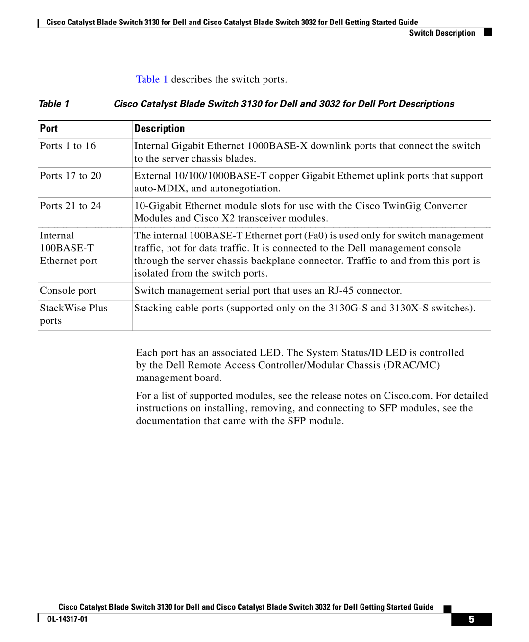
In terms of connectivity, both models are equipped with multiple 10/25/40/100 Gigabit Ethernet ports, allowing for a broad range of network configurations. They are also built with energy efficiency in mind, contributing to sustainability efforts without compromising performance.
Furthermore, these switches are designed for ease of management and monitoring. Cisco's DNA Center facilitates centralized management across the network, allowing IT administrators to automate processes and implement policies quickly and effectively.
In summary, the Cisco 3032 and 3130 series represent a significant advancement in network technology, combining high performance and advanced features tailored for the challenges of contemporary networking. With their ability to efficiently handle increasing data demands and support complex operations, these models remain at the forefront of Cisco's commitment to meeting the evolving needs of businesses globally.

