March 2002
Internal CompactFlash Memory Card Installation and Removal
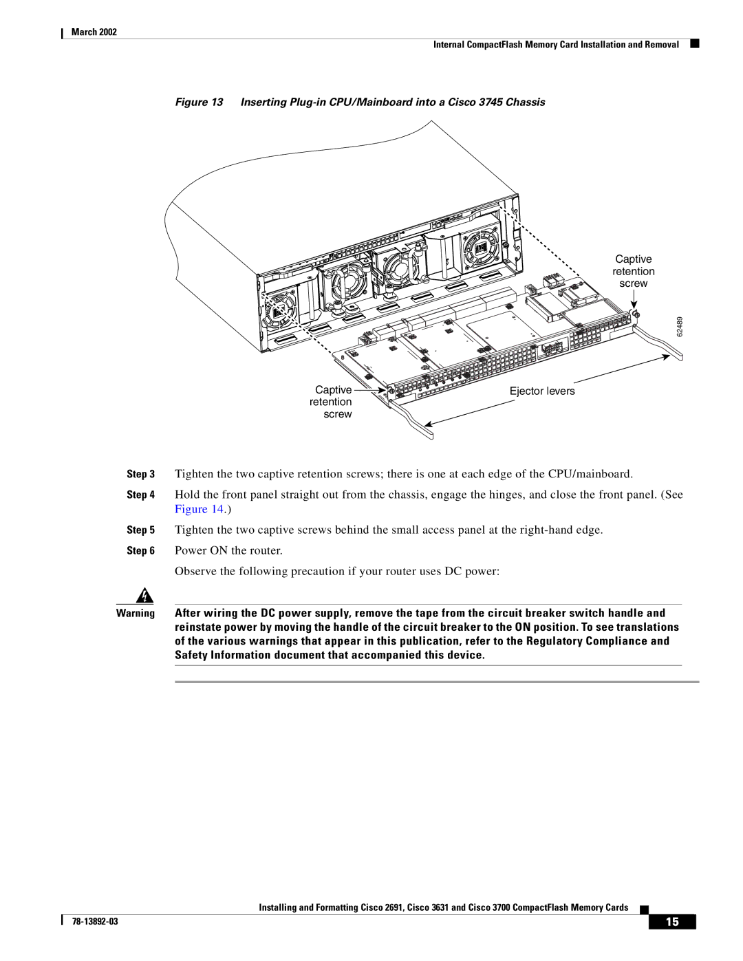
Figure 13 Inserting Plug-in CPU/Mainboard into a Cisco 3745 Chassis
Captive
retention
screw
62489
Captive | Ejector levers |
retention |
|
screw |
|
Step 3 Tighten the two captive retention screws; there is one at each edge of the CPU/mainboard.
Step 4 Hold the front panel straight out from the chassis, engage the hinges, and close the front panel. (See Figure 14.)
Step 5 Tighten the two captive screws behind the small access panel at the
Observe the following precaution if your router uses DC power:
Warning After wiring the DC power supply, remove the tape from the circuit breaker switch handle and reinstate power by moving the handle of the circuit breaker to the ON position. To see translations of the various warnings that appear in this publication, refer to the Regulatory Compliance and Safety Information document that accompanied this device.
Installing and Formatting Cisco 2691, Cisco 3631 and Cisco 3700 CompactFlash Memory Cards
| 15 |
| |
|
|