Chapter 1 Concepts
EM Objects and Interfaces
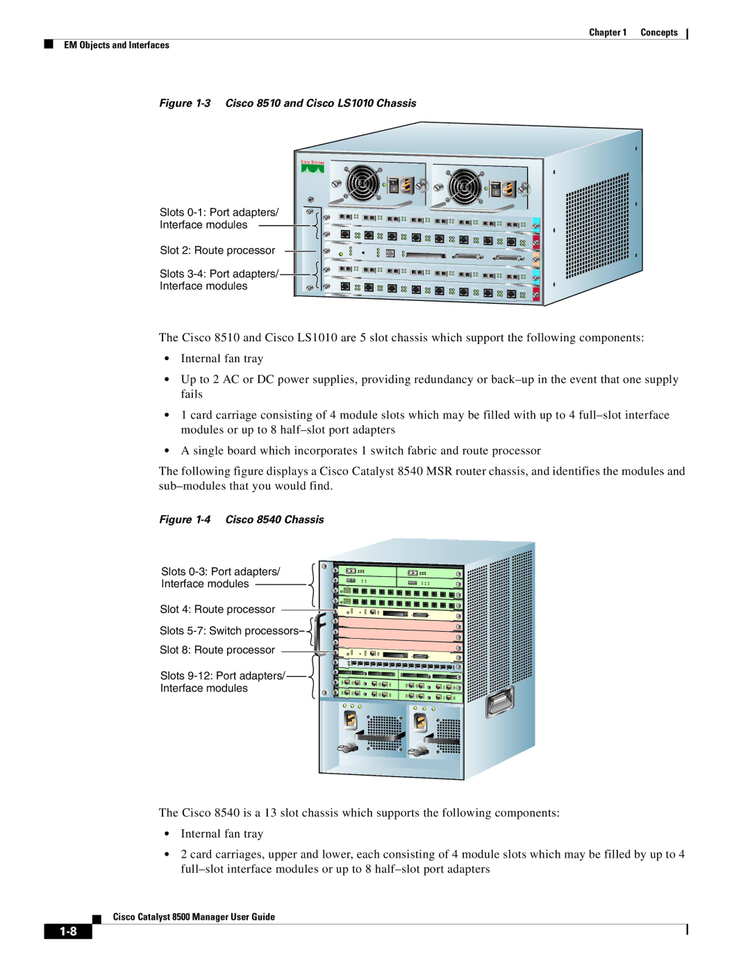
Figure 1-3 Cisco 8510 and Cisco LS1010 Chassis
Slots ![]() Interface modules
Interface modules
Slot 2: Route processor
0
1
2
|
| 100Mbps Tx |
100 Base Fx |
| LINK Rx |
FAST ETHERNET MODULE |
| |
STATUS | 1 | 100Mbps Tx |
|
| LINK Rx |
STATUS |
|
|
2
100Mbps Tx
LINK Rx
100Mbps Tx
LINK Rx
3
100Mbps Tx
LINK Rx
100Mbps Tx
LINK Rx
4
100Mbps Tx
LINK Rx
100Mbps Tx
LINK Rx
5
100Mbps Tx
LINK Rx
100Mbps Tx
LINK Rx
6
100Mbps Tx
LINK Rx
100Mbps Tx
LINK Rx
7
100Mbps Tx
LINK Rx
100Mbps Tx
LINK Rx
8
100Mbps Tx
LINK Rx
100Mbps Tx
LINK Rx
Slots ![]()
3
4
|
| 100Mbps Tx |
100 Base Fx |
| LINK Rx |
FAST ETHERNET MODULE |
| |
STATUS | 1 | 100Mbps Tx |
| ||
|
| LINK Rx |
2
100Mbps Tx
LINK Rx
100Mbps Tx
LINK Rx
3
100Mbps Tx
LINK Rx
100Mbps Tx
LINK Rx
4
100Mbps Tx
LINK Rx
100Mbps Tx
LINK Rx
5
100Mbps Tx
LINK Rx
100Mbps Tx
LINK Rx
6
100Mbps Tx
LINK Rx
100Mbps Tx
LINK Rx
7
100Mbps Tx
LINK Rx
100Mbps Tx
LINK Rx
8
100Mbps Tx
LINK Rx
100Mbps Tx
LINK Rx
The Cisco 8510 and Cisco LS1010 are 5 slot chassis which support the following components:
•Internal fan tray
•Up to 2 AC or DC power supplies, providing redundancy or
•1 card carriage consisting of 4 module slots which may be filled with up to 4
•A single board which incorporates 1 switch fabric and route processor
The following figure displays a Cisco Catalyst 8540 MSR router chassis, and identifies the modules and
Figure 1-4 Cisco 8540 Chassis
Slots
Interface modules
Slot 4: Route processor
Slots
Slot 8: Route processor
Slots
Interface modules
o![]()
![]()
![]()
![]()
![]()
![]()
![]()
![]()
![]()
![]()
![]()
![]()
![]()
![]()
![]()
![]()
![]()
![]()
![]()
![]()
![]()
![]()
![]()
![]()
![]()
![]()
![]()
![]() o
o![]()
![]()
![]()
![]()
![]()
![]()
![]()
![]()
![]()
![]()
The Cisco 8540 is a 13 slot chassis which supports the following components:
•Internal fan tray
•2 card carriages, upper and lower, each consisting of 4 module slots which may be filled by up to 4
Cisco Catalyst 8500 Manager User Guide
