Installing the Antenna
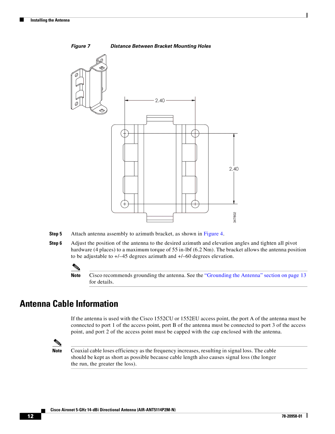
Figure 7 | Distance Between Bracket Mounting Holes |
2.40
2.40
347802
Step 5 Attach antenna assembly to azimuth bracket, as shown in Figure 4.
Step 6 Adjust the position of the antenna to the desired azimuth and elevation angles and tighten all pivot hardware (4 places) to a maximum torque of 55
Note Cisco recommends grounding the antenna. See the “Grounding the Antenna” section on page 13 for details.
Antenna Cable Information
If the antenna is used with the Cisco 1552CU or 1552EU access point, the port A of the antenna must be connected to port 1 of the access point, port B of the antenna must be connected to port 3 of the access point, and port 2 of the access point must be capped with the cap enclosed with the antenna.
Note Coaxial cable loses efficiency as the frequency increases, resulting in signal loss. The cable should be kept as short as possible because cable length also causes signal loss (the longer the run, the greater the loss).
Cisco Aironet
12 |
| |
|