ASR 901 specifications
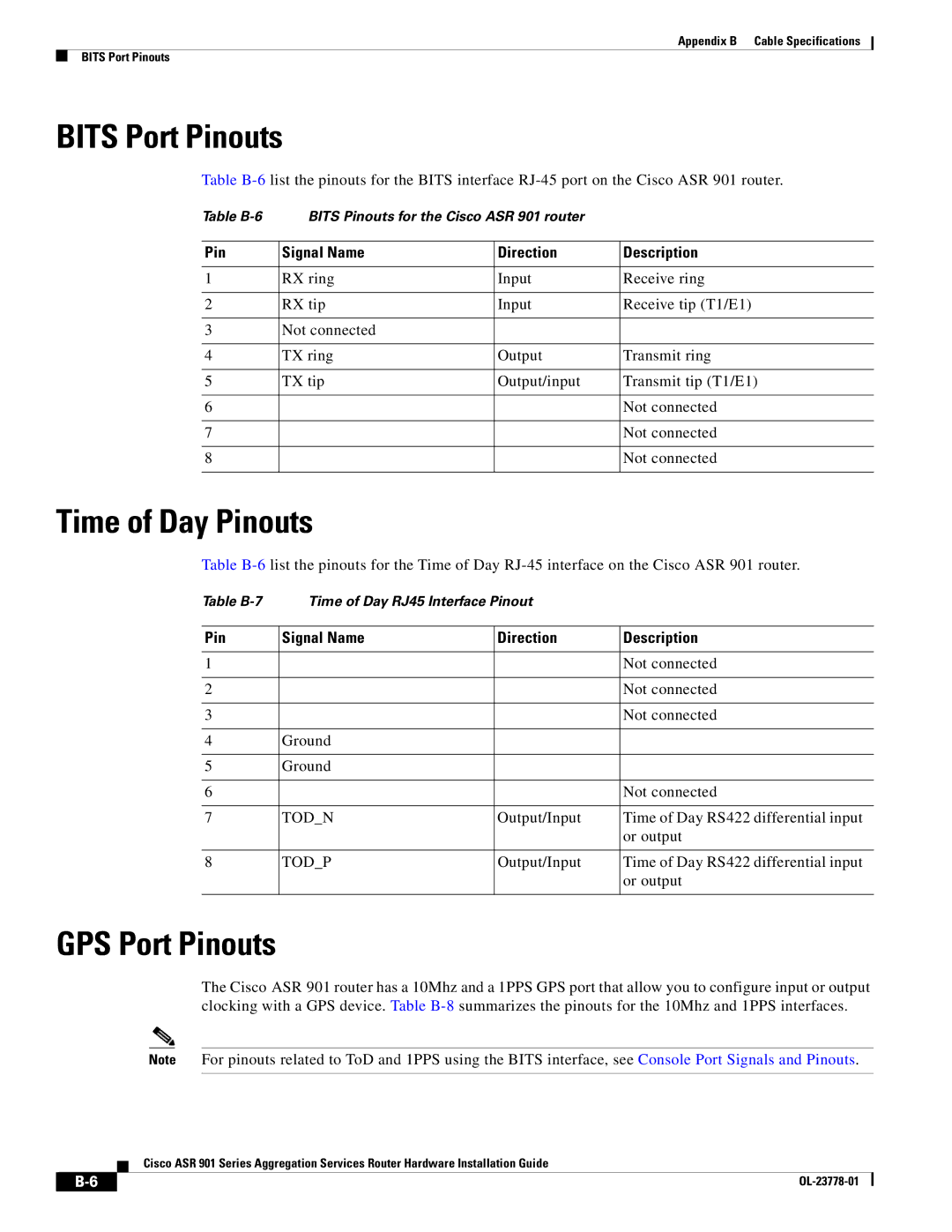
Cisco Systems ASR 901 is an advanced aggregation services router that is designed to meet the needs of service providers and enterprise networks. It offers a versatile platform suitable for various deployment scenarios ranging from mobile backhaul and broadband aggregation to IP edge routing. The ASR 901 is known for its compact size, energy efficiency, and robust performance, making it a preferred choice for operators looking to enhance their network infrastructure.One of the main features of the Cisco ASR 901 is its small form factor, which facilitates installation in space-constrained environments. Its design allows for easy deployment in both indoor and outdoor settings, making it ideal for applications such as cell site backhaul and remote locations. The router supports a wide range of interfaces, including Ethernet and T1/E1, providing flexibility in connecting different network types.
The ASR 901 is built on Cisco's IOS XR software, ensuring a highly reliable and secure operating environment. This software is known for its scalability and robustness, providing operators with the ability to support large numbers of subscribers and high traffic volumes. The router also supports system redundancy features, ensuring continuous service availability and minimizing downtime.
In terms of performance, the Cisco ASR 901 delivers high throughput and low latency, which are crucial for delivering quality services like voice, video, and data. With its support for advanced network technologies such as MPLS and IPv6, the ASR 901 can effectively manage complex networking requirements while accommodating future growth.
Security is also a key consideration with the ASR 901. It includes features such as advanced encryption, access control lists, and intrusion prevention systems, aimed at protecting the integrity of network communications. Moreover, its support for Virtual LAN (VLAN) tagging and Quality of Service (QoS) mechanisms allows for efficient traffic management and prioritization, ensuring that critical applications receive the necessary bandwidth.
Furthermore, Cisco provides comprehensive management tools for the ASR 901, allowing network administrators to easily monitor and configure the router. Features like SNMP and NetFlow enable operators to gain insights into network performance and usage patterns, facilitating proactive management of their environments.
Overall, the Cisco Systems ASR 901 stands out as a powerful and flexible router, designed to meet the evolving demands of modern networks. Its combination of compact design, scalability, and advanced features positions it as an ideal solution for service providers and enterprises seeking reliable and efficient network solutions.

