After you have replaced the connector locks, reenable the interfaces by entering the command no shutdown, as shown in the following partial example.
interface ethernet 1/1
no shutdown
^Z
You can display the current state of an individual Ethernet interface by entering the command show interface type slot/port, or you can omit the interface type and address to display interface information for all network interfaces in the router.
Following is a partial, sample session that displays information about the first Ethernet port (port 0) on an EIP installed in slot 1. Only the first few lines of the display are included in the example, because the state of the interface (up or down) is indicated on the first line of the display.
Router>show interface ethernet 1/0
Ethernet1/0 is administratively down, line protocol is down Hardware is cxBus Ethernet, address is 0000.0c (bia.0c02.d0cc) (display text deleted)
Router>show int eth 1/1
Ethernet1/1 is up, line protocol is up
Hardware is cxBus Ethernet, address is 0000.0c (bia.0c02.d0ce) (display text deleted)
You can also use the show configuration command to display the status of all interfaces. Refer to the 9.17 Addendum to the Router Products Configuration and Reference publication for complete command descriptions and instructions.
Removing the Slide Lock
The bracket for
Step 1: Ensure that the
Step 2: On the first connector port to be changed, use the
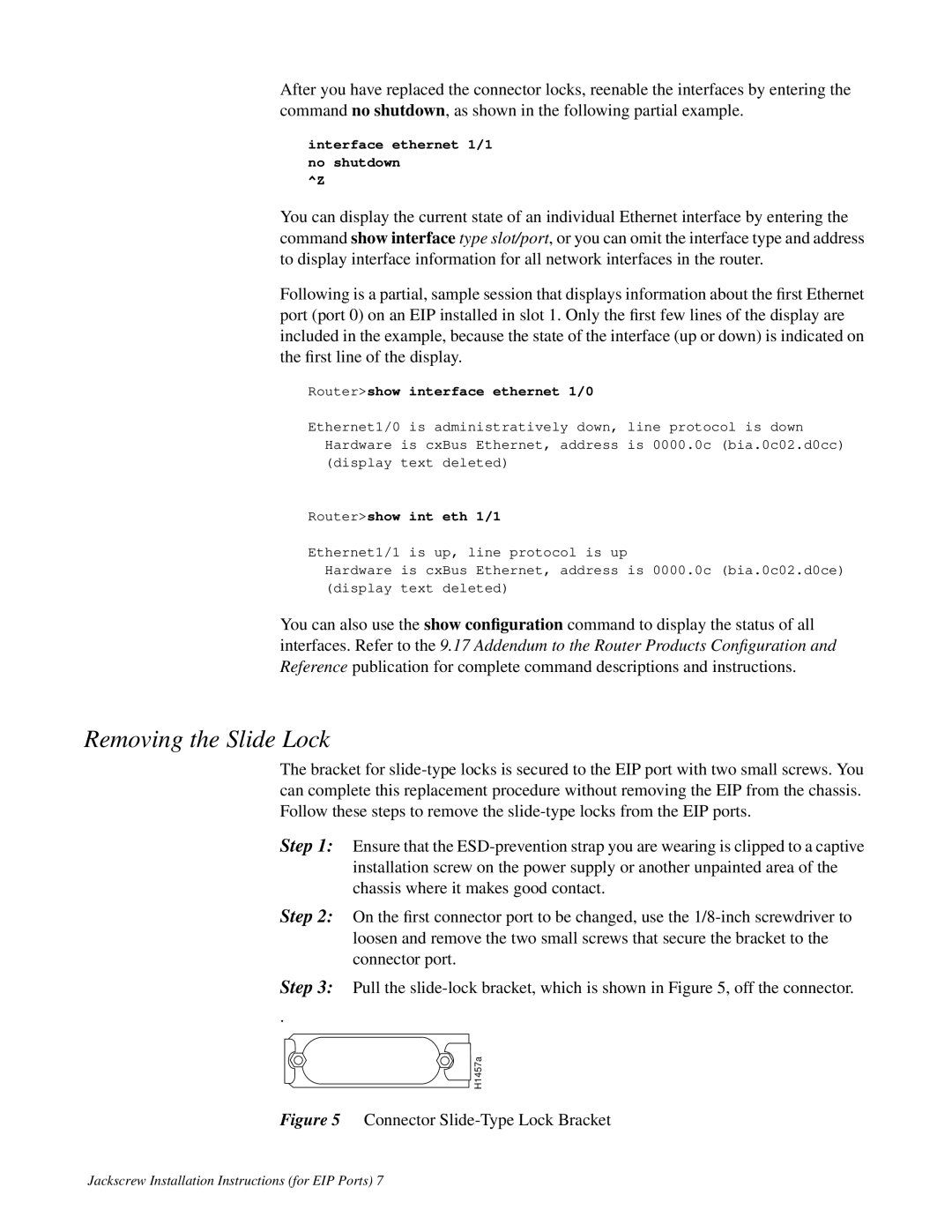
Step 3: Pull the
.
![]() H1457a
H1457a
Figure 5 Connector Slide-Type Lock Bracket
Jackscrew Installation Instructions (for EIP Ports) 7