ME 6500 specifications
The Cisco Systems ME 6500 is a sophisticated Ethernet switch designed to cater to the demanding needs of service providers and large enterprises. Engineered to deliver high performance and reliability, the ME 6500 series is ideal for both metro Ethernet applications and data center environments. One of its standout features is the ability to handle massive bandwidth, making it suitable for high-capacity networks. The switch supports a range of Ethernet services that facilitate seamless connectivity and network expansion.At the core of the ME 6500 is its ability to provide Layer 2 and Layer 3 functionalities, which allows for flexibility in network design. This dual-layer capability enhances the switch's efficiency in managing traffic and ensures optimal forwarding of data packets. In addition, the ME 6500 series supports a wide range of Ethernet interfaces, including 10 Gigabit and 1 Gigabit Ethernet ports, which are essential for accommodating diverse bandwidth requirements.
One of the defining characteristics of the Cisco ME 6500 is its scalability. It supports up to 192 10 Gigabit Ethernet ports within a single chassis, enabling organizations to expand their network without compromising performance. Furthermore, the switch includes advanced Quality of Service (QoS) features that allow for traffic prioritization, which is crucial for maintaining the performance of voice and video services across the network.
The ME 6500 switch is also equipped with robust security features, including Access Control Lists (ACLs) and secure management protocols. These features protect sensitive data as it traverses the network, ensuring that only authorized users have access to critical resources. Management of the switch is simplified through Cisco’s management tools, allowing network administrators to monitor, configure, and troubleshoot the device efficiently.
Additionally, the switch supports various redundancy protocols, including Rapid Spanning Tree Protocol (RSTP) and Link Aggregation Control Protocol (LACP), ensuring high availability and minimizing downtime.
Overall, the Cisco ME 6500 is a powerful and versatile solution that meets the heavy demands of modern network environments, delivering outstanding performance, security, and scalability for both service providers and large enterprises. Its advanced features make it a go-to choice for organizations looking to future-proof their networking infrastructure.

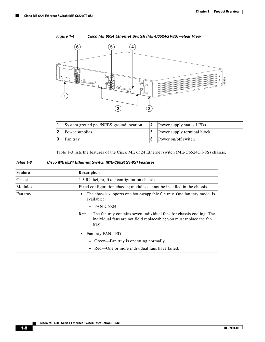
 147978