OC-12/STM-14 specifications
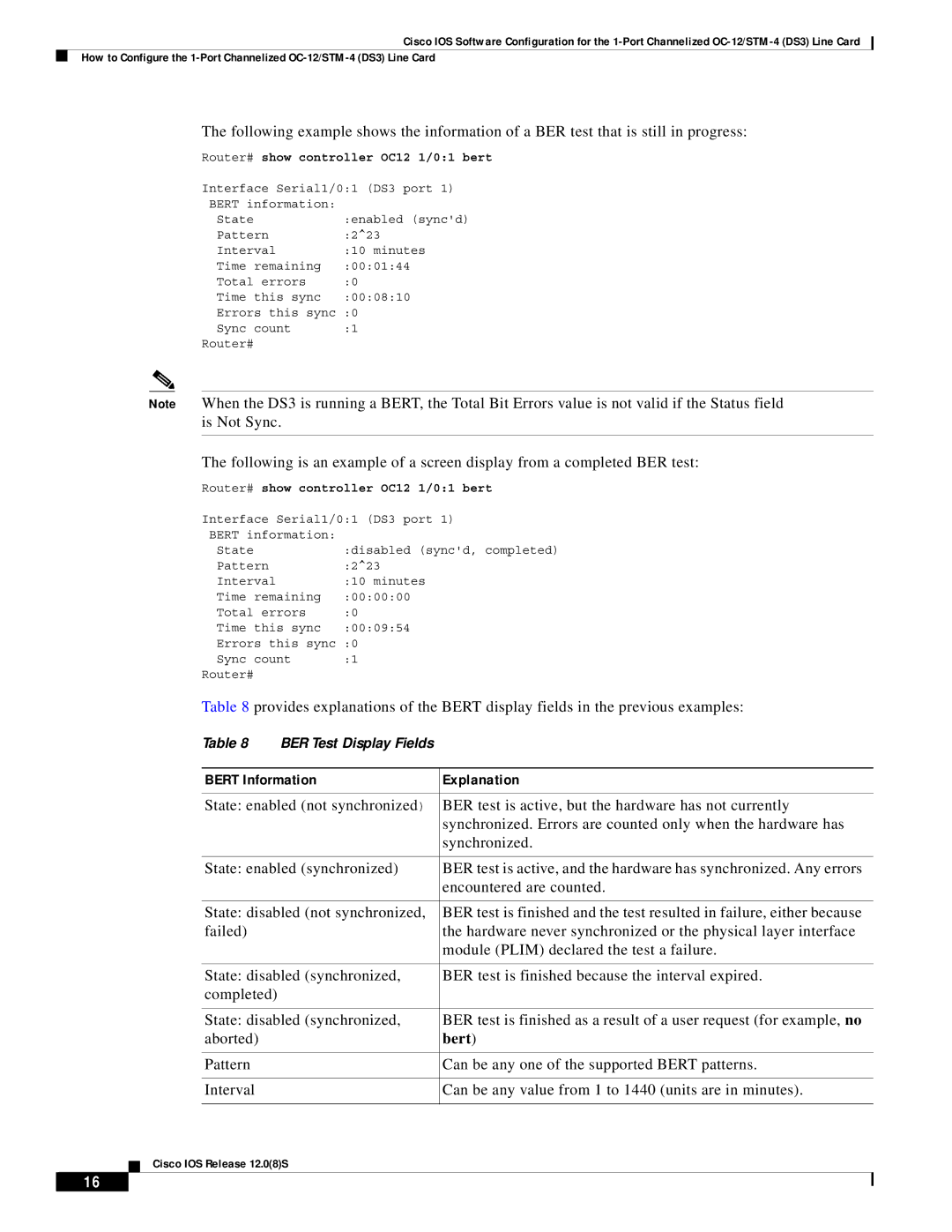
Cisco Systems OC-12/STM-14 is a high-performance networking solution designed to meet the demands of modern telecommunications and data transport applications. Operating at a data rate of 622 Mbps, the OC-12 (Optical Carrier level 12) and STM-14 (Synchronous Transport Module level 14), this technology provides a reliable and efficient method for organizations to transmit large volumes of data over fiber optic networks.One of the key features of the OC-12/STM-14 system is its capability for high-speed data transfer. This makes it an ideal choice for service providers looking to deliver broadband services, video streaming, and other bandwidth-intensive applications. With support for multiple protocols, including SONET (Synchronous Optical Network) and SDH (Synchronous Digital Hierarchy), the OC-12/STM-14 can facilitate smooth communication and interoperability between various network devices.
Another significant characteristic of the OC-12/STM-14 is its scalability. Organizations can easily scale their networks by adding additional OC-12/STM-14 connections, accommodating their growing bandwidth needs without a complete overhaul of existing infrastructure. This flexibility is essential for businesses that expect fluctuations in data traffic or are anticipating future expansion.
Additionally, Cisco's OC-12/STM-14 employs advanced error correction and fault tolerance features, ensuring high reliability and minimal downtime. It supports sophisticated monitoring and network management capabilities, allowing administrators to proactively manage network performance and troubleshoot potential issues before they affect service quality.
Security is also a critical aspect of the OC-12/STM-14 architecture. Cisco incorporates robust security protocols to safeguard sensitive data during transmission, ensuring compliance with industry standards and protecting against unauthorized access.
In terms of compatibility, the Cisco OC-12/STM-14 integrates seamlessly with existing infrastructure and can work alongside various routing platforms. This compatibility significantly reduces the cost and complexity associated with upgrading legacy systems.
Ultimately, Cisco Systems OC-12/STM-14 offers a powerful solution for enterprises and service providers looking to enhance their networking capabilities. With its high-speed data transfer, scalability, reliability, and security features, it stands as a cornerstone technology in advanced telecommunications and data networking.

