Connecting Cisco Voice Network Modules to the Network
IP Communications
Step 2 Hold the PVDM2 module with the polarization notch on the right, near the back of the chassis, with the connector edge at the bottom. (See Figure 18.)
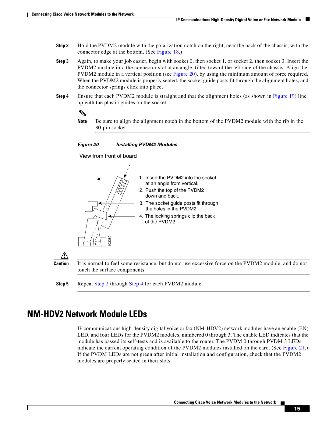
Step 3 Again, to make your job easier, begin with socket 0, then socket 1, or socket 2, then socket 3. Insert the PVDM2 module into the connector slot at an angle, tilted toward the left side of the chassis. Align the PVDM2 module in a vertical position (see Figure 20), by using the minimum amount of force required. When the PVDM2 module is properly seated, the socket guide posts fit through the alignment holes, and the connector springs click into place.
Step 4 Ensure that each PVDM2 module is straight and that the alignment holes (as shown in Figure 19) line up with the plastic guides on the socket.
Note Be sure to align the alignment notch in the bottom of the PVDM2 module with the rib in the
Figure 20 Installing PVDM2 Modules
View from front of board
103280 |
1.Insert the PVDM2 into the socket at an angle from vertical.
2.Push the top of the PVDM2 down and back.
3.The socket guide posts fit through the holes in the PVDM2.
4.The locking springs clip the back of the PVDM2.
Caution It is normal to feel some resistance, but do not use excessive force on the PVDM2 module, and do not touch the surface components.
Step 5 Repeat Step 2 through Step 4 for each PVDM2 module.
NM-HDV2 Network Module LEDs
IP communications
Connecting Cisco Voice Network Modules to the Network
15