Connecting Cisco Voice Network Modules to the Network
IP Communications
Figure 17 PVDM2 Module Slot Locations
3 | 2 |
1 | 0 |
| 95199 |
PVDM2 Module Orientation
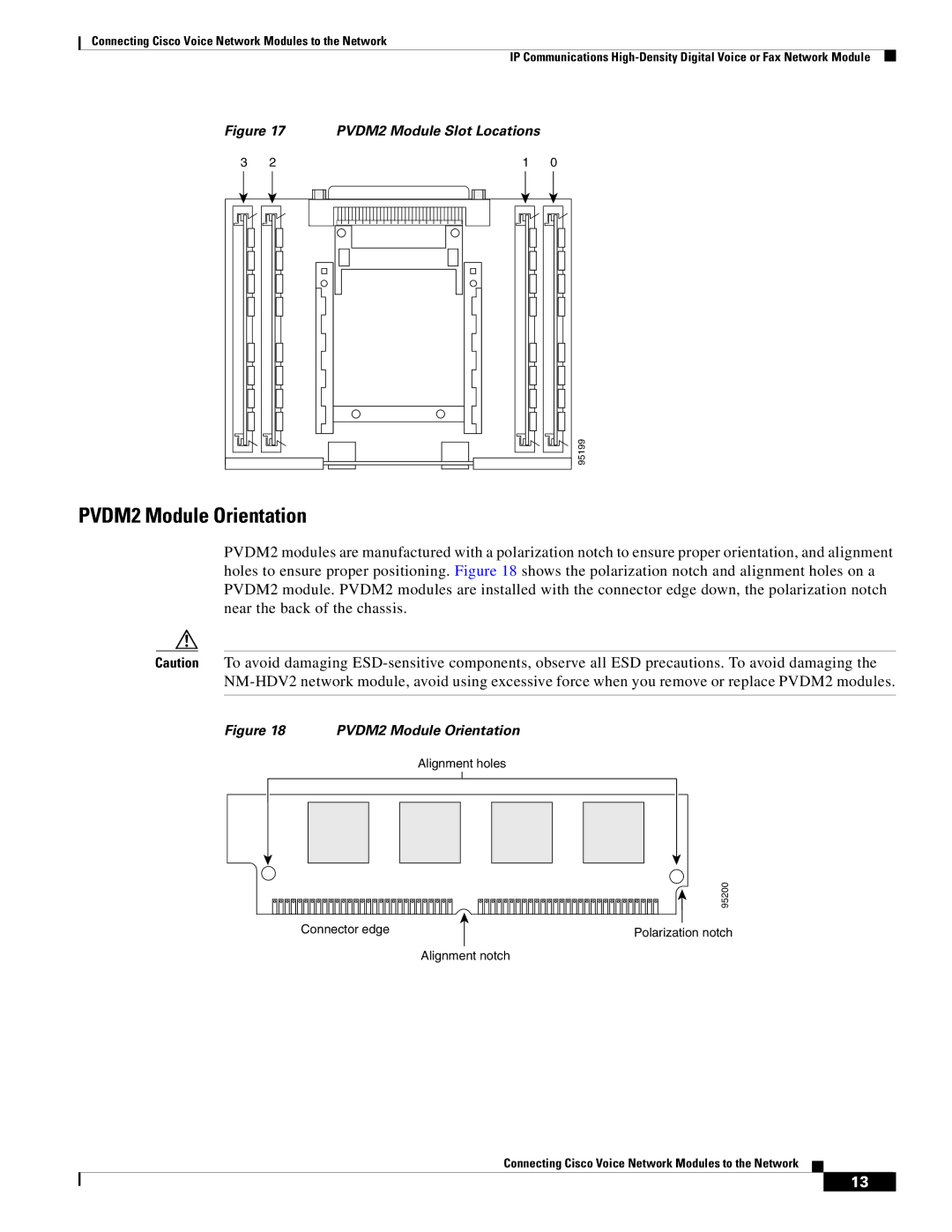
PVDM2 modules are manufactured with a polarization notch to ensure proper orientation, and alignment holes to ensure proper positioning. Figure 18 shows the polarization notch and alignment holes on a PVDM2 module. PVDM2 modules are installed with the connector edge down, the polarization notch near the back of the chassis.
Caution To avoid damaging
Figure 18 PVDM2 Module Orientation
Alignment holes
| 95200 |
Connector edge | Polarization notch |
| Alignment notch |
Connecting Cisco Voice Network Modules to the Network
13