Connecting Cisco Voice Network Modules to the Network
Voice Network Module LEDs
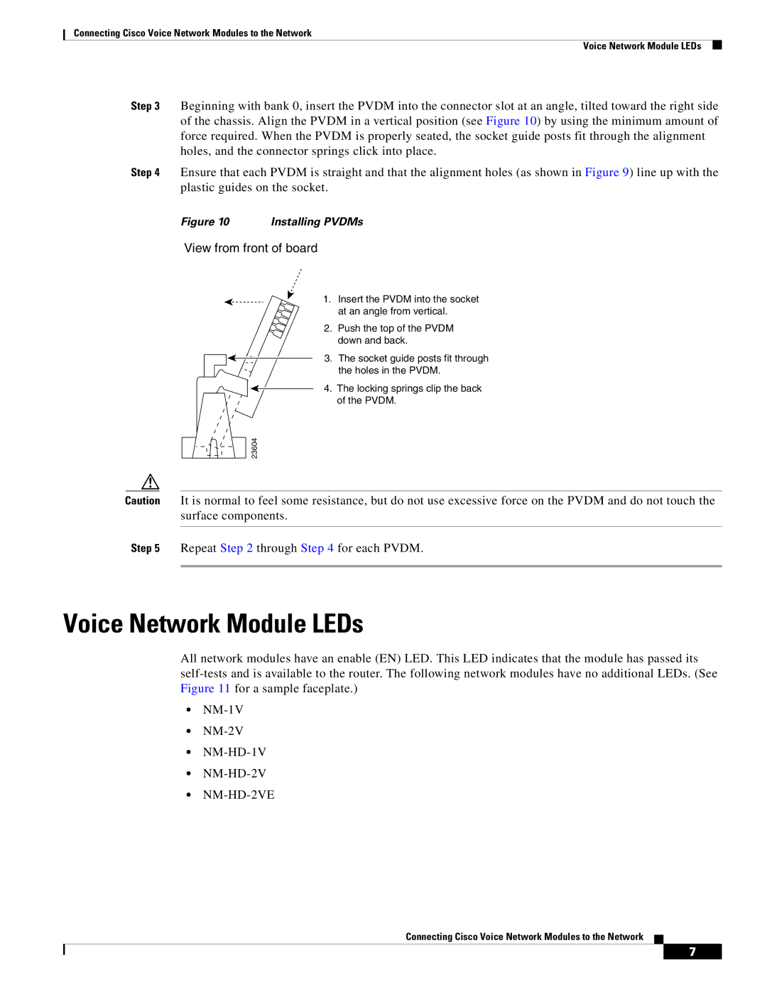
Step 3 Beginning with bank 0, insert the PVDM into the connector slot at an angle, tilted toward the right side of the chassis. Align the PVDM in a vertical position (see Figure 10) by using the minimum amount of force required. When the PVDM is properly seated, the socket guide posts fit through the alignment holes, and the connector springs click into place.
Step 4 Ensure that each PVDM is straight and that the alignment holes (as shown in Figure 9) line up with the plastic guides on the socket.
Figure 10 | Installing PVDMs |
View from front of board
1. Insert the PVDM into the socket at an angle from vertical.
2. Push the top of the PVDM down and back.
3. The socket guide posts fit through the holes in the PVDM.
4. The locking springs clip the back of the PVDM.
23604
Caution It is normal to feel some resistance, but do not use excessive force on the PVDM and do not touch the surface components.
Step 5 Repeat Step 2 through Step 4 for each PVDM.
Voice Network Module LEDs
All network modules have an enable (EN) LED. This LED indicates that the module has passed its
•
•
•
•
•NM-HD-2VE
Connecting Cisco Voice Network Modules to the Network
7