Chapter 1 Overview
Cables, Connectors, and Pinouts
The green enabled LED on the port adapter indicates that the motherboard is enabled and receiving power, and that the port adapter is ready for operation.
The following conditions must be met before the enabled LED goes on:
•The
•The
•The bus recognizes the
If any of these conditions is not met, or if the initialization fails for other reasons, the enabled LED does not go on.
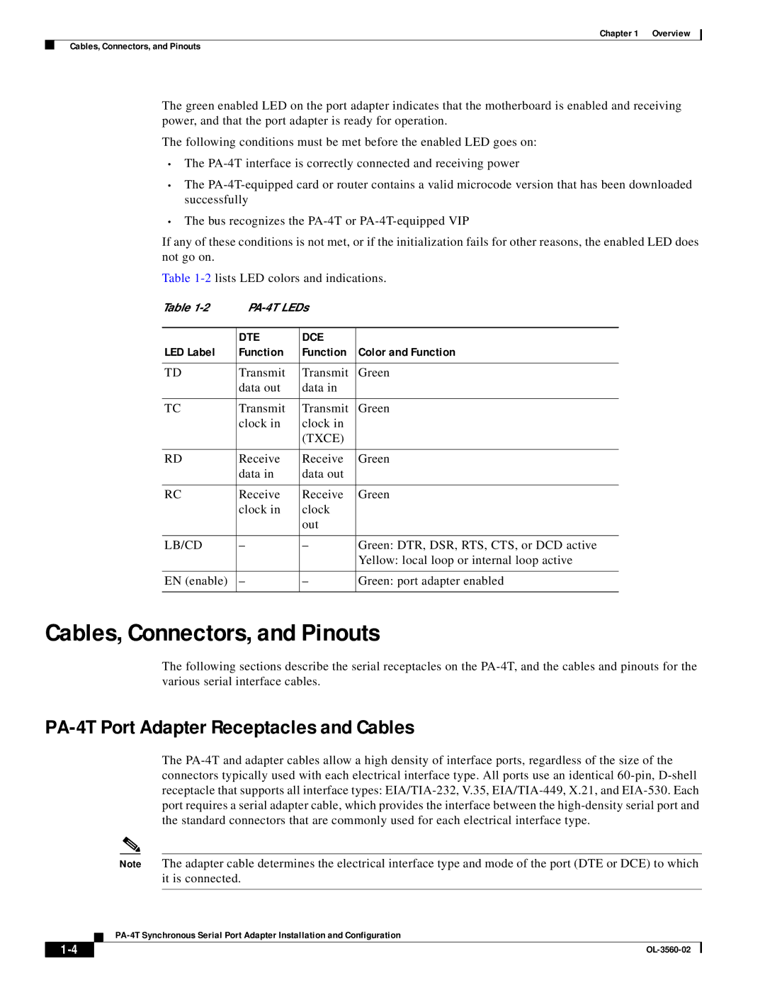
Table
Table |
| ||
|
|
|
|
| DTE | DCE |
|
LED Label | Function | Function | Color and Function |
|
|
|
|
TD | Transmit | Transmit | Green |
| data out | data in |
|
|
|
|
|
TC | Transmit | Transmit | Green |
| clock in | clock in |
|
|
| (TXCE) |
|
|
|
|
|
RD | Receive | Receive | Green |
| data in | data out |
|
|
|
|
|
RC | Receive | Receive | Green |
| clock in | clock |
|
|
| out |
|
|
|
|
|
LB/CD | – | – | Green: DTR, DSR, RTS, CTS, or DCD active |
|
|
| Yellow: local loop or internal loop active |
|
|
|
|
EN (enable) | – | – | Green: port adapter enabled |
|
|
|
|
Cables, Connectors, and Pinouts
The following sections describe the serial receptacles on the
PA-4T Port Adapter Receptacles and Cables
The
Note The adapter cable determines the electrical interface type and mode of the port (DTE or DCE) to which it is connected.
| ||
|