Chapter 1 Overview
Synchronous Serial Specifications
Synchronous Serial Specifications
The PA-4T provides up to four synchronous serial interfaces. Each interface allows a maximum bandwidth of 2.048 Mbps; the speed depends on the type of electrical interface used. Use EIA/TIA-232 for speeds of 64 kilobits per second (kbps) and below, and use X.21, EIA/TIA-449, V.35, or EIA-530 for higher speeds.
Serial signals can travel a limited distance at any given bit rate; generally, the slower the baud rate, the greater the distance. All serial signals are subject to distance limits beyond which a signal degrades significantly or is completely lost.
Table 1-1lists the recommended (standard) maximum speeds and distances for each PA-4T serial interface type. The recommended maximum rate for V.35 is 2,048 Mbps.
Table 1-1 Standards for Transmission Speed Versus Distance
| EIA/TIA-232 | | EIA/TIA-449, X.21, V.35, EIA-530 |
| Distances | | | Distances | |
| | | | | |
Rate (bps) | Feet | Meters | | Feet | Meters |
| | | | | |
2400 | 200 | 60 | | 4,100 | 1,250 |
| | | | | |
4800 | 100 | 30 | | 2,050 | 625 |
| | | | | |
9600 | 50 | 15 | | 1,025 | 312 |
| | | | | |
19200 | 25 | 7.6 | | 513 | 156 |
| | | | | |
38400 | 12 | 3.7 | | 256 | 78 |
| | | | | |
56000 | 8.6 | 2.6 | | 102 | 31 |
| | | | | |
1544000 (T1) | – | – | | 50 | 15 |
| | | | | |
Balanced drivers allow EIA/TIA-449 signals to travel greater distances than EIA/TIA-232. The recommended distance limits for EIA/TIA-449 shown in Table 1-1are also valid for V.35, X.21, and EIA-530. EIA/TIA-449 and EIA-530 support 2.048-Mbps rates, and V.35 supports 2.048-Mbps rates without any problems; we do not recommend exceeding published specifications for transmission speed versus distance. Do so at your own risk.
LEDs
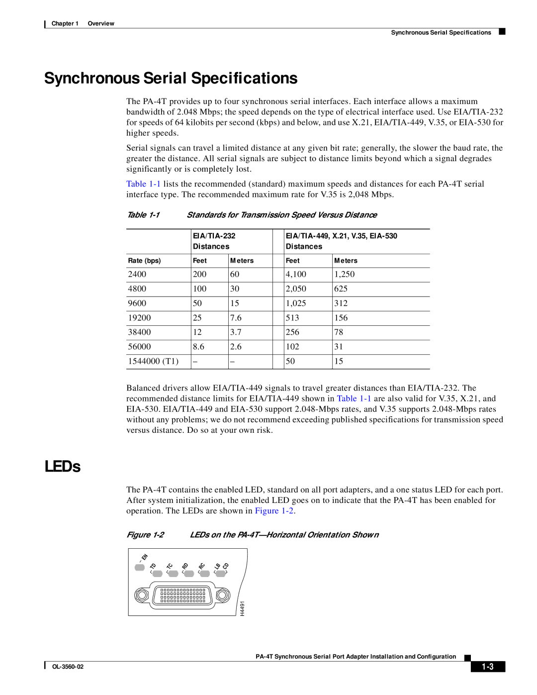
The PA-4T contains the enabled LED, standard on all port adapters, and a one status LED for each port. After system initialization, the enabled LED goes on to indicate that the PA-4T has been enabled for operation. The LEDs are shown in Figure 1-2.
Figure 1-2 LEDs on the PA-4T—Horizontal Orientation Shown
H4491
| | | | | | |
| | PA-4T Synchronous Serial Port Adapter Installation and Configuration | | |
| | |
| OL-3560-02 | | | 1-3 | |
| | | |

