Chapter 1 Overview
Port Adapter Slot Locations on the Supported Platforms
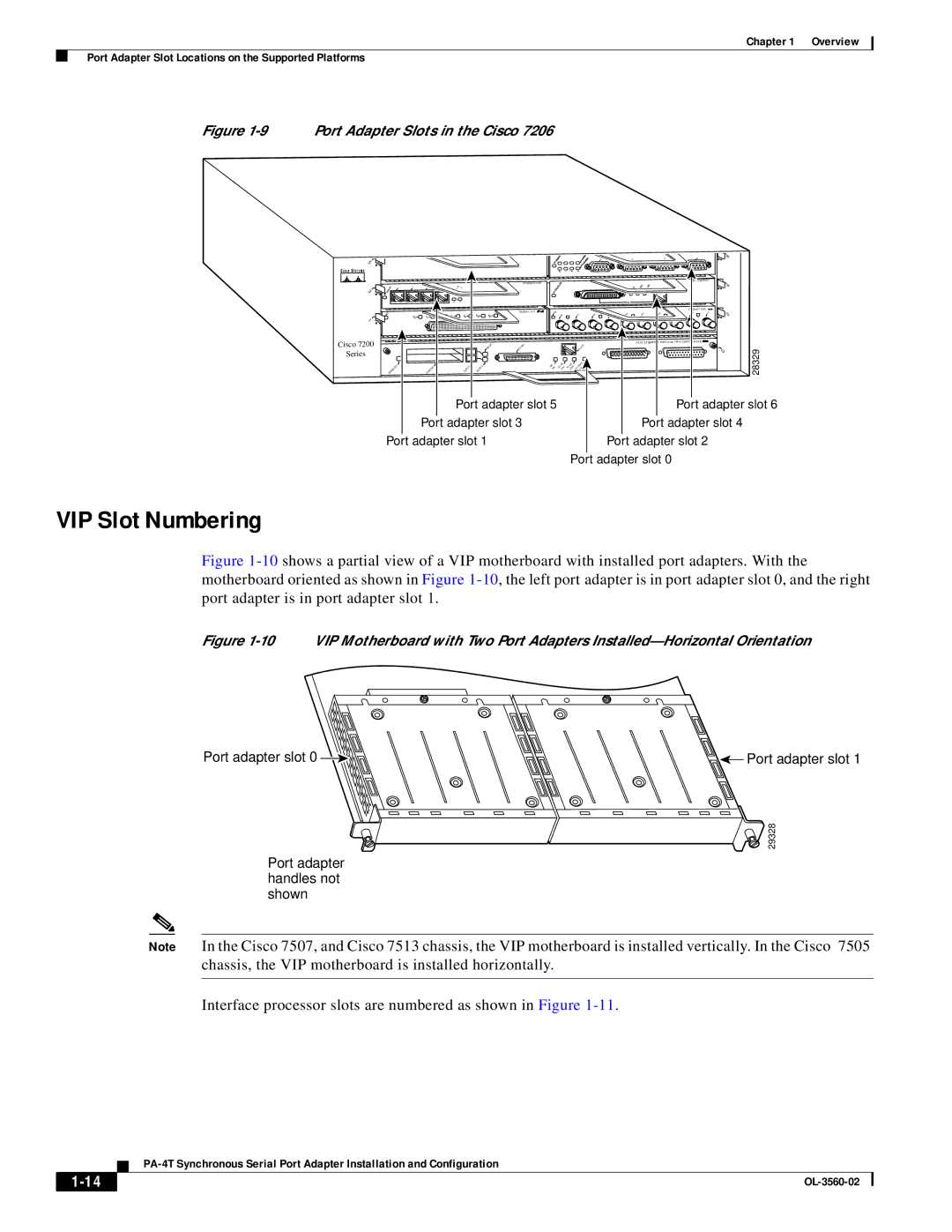
Figure 1-9 Port Adapter Slots in the Cisco 7206
5
3
1
EN
0 | 1 |
2 | 3 | 4 |
ETHERNET 10BT
5 | 6 | 7 |
ENABLED | MII | LINK | RJ45 |
|
|
|
|
| 0 |
EN | TX | RX | TX | RX | TX |
RX | |||||
| 0 |
| 1 |
| 2 |
|
|
|
| 6 |
|
| FAST ETHERNET |
| |
|
|
|
| 4 |
|
|
|
| |
RX | TX | RX | TX | 2 |
| 3 | 4 |
|
|
Cisco 7200 Series
|
|
|
| SLOT | 1 | FE | MII |
|
|
|
| RJ | FAST ETHERNET INPUT/OUTPUT CONTROLLER |
|
|
|
|
|
|
|
|
|
|
|
|
| 28329 | ||
|
|
|
|
|
|
|
|
|
|
|
|
| 0 | |
|
|
|
| 0 |
|
| MII | RJ |
| RJ |
| PWR |
| |
ENABLED | PCMCIA |
|
|
|
|
|
|
|
| |||||
EJECT | SLOT |
|
|
| EN |
| EN |
| LINK 1O | OK |
| |||
|
| Port adapter slot 5 |
|
|
|
|
| Port adapter slot 6 | ||||||
| Port adapter slot 3 |
|
|
|
|
| Port adapter slot 4 |
| ||||||
Port adapter slot 1 |
|
|
|
|
|
|
|
| Port adapter slot 2 |
| ||||
|
|
|
|
|
|
|
|
|
|
| Port adapter slot 0 |
| ||
VIP Slot Numbering
Figure 1-10 shows a partial view of a VIP motherboard with installed port adapters. With the motherboard oriented as shown in Figure 1-10, the left port adapter is in port adapter slot 0, and the right port adapter is in port adapter slot 1.
Figure 1-10 VIP Motherboard with Two Port Adapters Installed—Horizontal Orientation
Port adapter slot 0 | Port adapter slot 1 |
| 29328 |
Port adapter |
|
handles not |
|
shown |
|
Note In the Cisco 7507, and Cisco 7513 chassis, the VIP motherboard is installed vertically. In the Cisco 7505 chassis, the VIP motherboard is installed horizontally.
