Chapter 1 Introducing the Cisco Wide Area Virtualization Engine 594 and 694
Hardware Features
Back Panel Components and LEDs
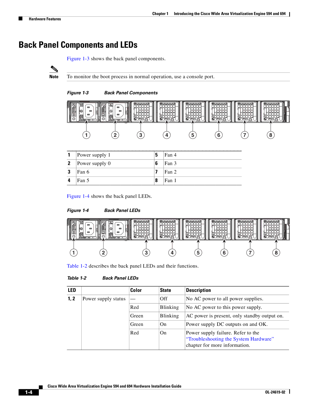
Figure 1-3 shows the back panel components.
Note To monitor the boot process in normal operation, use a console port.
Figure 1-3 Back Panel Components
| 1 | 2 | 3 |
| 4 | 5 | 6 | 7 | 8 |
|
|
|
|
|
|
|
|
|
|
1 | Power supply 1 |
|
| 5 | Fan 4 |
|
|
|
|
|
|
|
|
|
|
|
|
|
|
2 | Power supply 0 |
|
| 6 | Fan 3 |
|
|
|
|
|
|
|
|
|
|
|
|
|
|
3 | Fan 6 |
|
| 7 | Fan 2 |
|
|
|
|
|
|
|
|
|
|
|
|
|
|
4 | Fan 5 |
|
| 8 | Fan 1 |
|
|
|
|
|
|
|
|
|
|
|
|
|
|
Figure 1-4 shows the back panel LEDs.
Figure | Back Panel LEDs |
|
|
|
|
|
|
1 | 2 | 3 | 4 | 5 | 6 | 7 | 8 |
Table
Table | Back Panel LEDs |
|
| ||
|
|
|
|
| |
LED |
|
| Color | State | Description |
|
|
|
|
| |
1, 2 | Power supply status | — | Off | No AC power to all power supplies. | |
|
|
|
|
|
|
|
|
| Red | Blinking | No AC power to this power supply. |
|
|
|
|
|
|
|
|
| Green | Blinking | AC power is present, only standby output on. |
|
|
|
|
|
|
|
|
| Green | On | Power supply DC outputs on and OK. |
|
|
|
|
|
|
|
|
| Red | On | Power supply failure. Refer to the |
|
|
|
|
| “Troubleshooting the System Hardware” |
|
|
|
|
| chapter for more information. |
|
|
|
|
|
|
Cisco Wide Area Virtualization Engine 594 and 694 Hardware Installation Guide
| ||
|
