Verifying the Installation
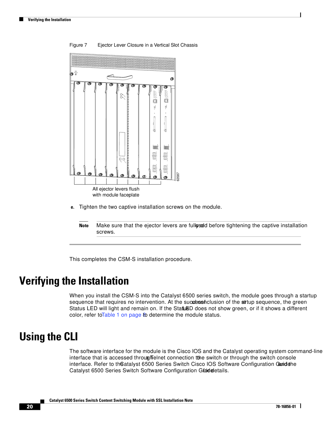
Figure 7 Ejector Lever Closure in a Vertical Slot Chassis
FAN
STATUS
![]() 24 PORT 100FX
24 PORT 100FX
![]()
STATUS
ACTIVE
N | SE |
EXT | LE |
| CT |
SU PE RV ISO R2
ST |
|
ATU | |
S | S |
YST | |
CO | EM |
NS | |
P | OLE |
WR | |
| MG |
RESET | |
| MT |
CON |
|
SO |
|
LE |
|
CO |
|
MODE PORT NSOLE |
|
PC |
|
MC |
|
IA |
|
EJE |
|
CT |
|
1% | 100 % S |
| witch |
| Lo |
| ad |
| POR |
| T1 |
| POR |
| T2 |
WS
SUPERVISOR2
ST |
|
ATU | |
S | S |
YST | |
CO | EM |
NS | |
P OLE | |
WR | |
RE | MG |
MT | |
SET | |
CONSOLE |
|
MODE PORT CONSOLE |
|
PCMCIA |
|
EJECT |
|
1% | 100% |
| Switch |
| Load |
| PORT1 |
| PORT 2 |
63587
All ejector levers flush with module faceplate
e.Tighten the two captive installation screws on the module.
Note Make sure that the ejector levers are fully closed before tightening the captive installation screws.
This completes the
Verifying the Installation
When you install the
Using the CLI
The software interface for the module is the Cisco IOS and the Catalyst operating system
Catalyst 6500 Series Switch Content Switching Module with SSL Installation Note
20 |
| |
|