Front Panel Description
Note You are required to make initial SSL daughter card configurations through a direct connection to the
LEDs
When the
Note For more information on the supervisor engine LEDs, refer to the Catalyst 6500 Series Switch Module Installation Guide.
|
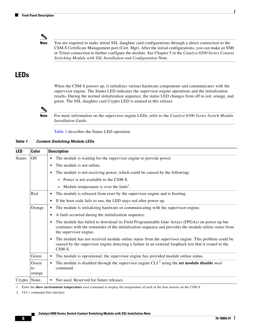
| Table 1 describes the Status LED operation. |
Table 1 | Content Switching Module LEDs | |
|
|
|
LED | Color | Description |
|
|
|
Status | Off | • The module is waiting for the supervisor engine to provide power. |
|
| • The module is not online. |
|
| • The module is not receiving power, which could be caused by the following: |
|
| – Power is not available to the |
|
| – Module temperature is over the limit1. |
| Red | • The module is released from reset by the supervisor engine and is booting. |
|
| • If the boot code fails to run, the LED stays red after power up. |
|
|
|
| Orange | • The module is initializing hardware or communicating with the supervisor engine. |
|
| • A fault occurred during the initialization sequence. |
|
| • The module has failed to download its Field Programmable Gate Arrays (FPGAs) on power up but |
|
| continues with the remainder of the initialization sequence and provides the module online status from |
|
| the supervisor engine. |
|
| • The module has not received module online status from the supervisor engine. This problem could be |
|
| caused by the supervisor engine detecting a failure in an external loopback test that it issued to the |
|
|
|
|
|
|
| Green | • The module is operational; the supervisor engine has provided module online status. |
|
|
|
| Green | • The module is disabled through the supervisor engine CLI 2 using the set module disable mod |
| to | command. |
| orange |
|
|
|
|
Crypto | None. | • Not used. Reserved for future releases. |
|
|
|
1.Enter the show environment temperature mod command to display the temperature of each of the four sensors on the
2.CLI =
Catalyst 6500 Series Switch Content Switching Module with SSL Installation Note
8 |
| |
|
