2960S, WSC2960S24TSSRF, 2960S-24TS-S, 2960 specifications
Cisco Systems 2960 series switches are a prominent solution in the networking landscape, known for their reliability, scalability, and feature-rich offerings. Ideal for small to medium-sized enterprises, these switches provide a robust foundation for network infrastructure, ensuring optimal performance and connectivity.One of the standout features of the Cisco 2960 series is its Layer 2 switching capabilities. The switches support multiple VLANs (Virtual Local Area Networks), allowing network administrators to segment traffic efficiently and enhance security protocols. This is crucial in modern networks where managing traffic and isolating sensitive information is a priority.
The Cisco 2960 series also incorporates advanced Quality of Service (QoS) features, enabling the prioritization of critical applications and services. This functionality ensures that time-sensitive data, such as voice and video traffic, maintains a high quality of service even in congested networks. With support for IEEE 802.1p and DSCP marking, administrators can fine-tune their network performance to meet specific organizational needs.
Power over Ethernet (PoE) is another significant characteristic of the Cisco 2960 series. This feature allows switches to deliver electrical power alongside data over Ethernet cables to devices such as IP phones, wireless access points, and surveillance cameras. With PoE, organizations can reduce clutter from power cables and increase deployment flexibility for various devices.
In terms of security, the Cisco 2960 series is equipped with a range of integrated security features. The switch supports port security, 802.1X authentication, and Access Control Lists (ACLs), providing robust defenses against unauthorized access and potential network vulnerabilities. These security measures are essential for protecting sensitive data and ensuring compliance with industry regulations.
Moreover, the Cisco 2960 series offers enhanced network management capabilities with Cisco's Intelligent Network Services. This includes support for Simple Network Management Protocol (SNMP), Cisco Prime, and Embedded Event Manager (EEM), allowing for efficient monitoring, troubleshooting, and policy enforcement across the network.
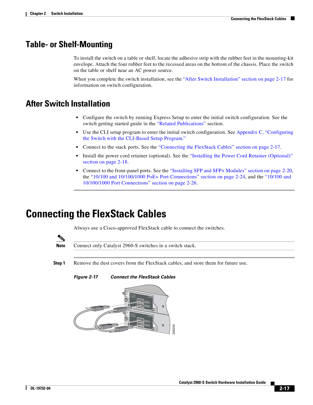
Additionally, the Cisco 2960 switches provide various models and configurations, catering to different networking needs. Options include models with varying port densities, uplink configurations, and stacking capabilities, making it easy for organizations to choose solutions that align perfectly with their requirements.
In summary, the Cisco 2960 series is a versatile and essential component of modern networking environments. Its advanced features, including Layer 2 support, QoS, PoE, robust security, and diverse management tools, make it an excellent choice for organizations looking to build a strong and secure network infrastructure.

