Chapter 2 Switch Installation

10/100 and 10/100/1000 PoE+ Port Connections

Warning Voltages that present a shock hazard may exist on Power over Ethernet (PoE) circuits if interconnections are made using uninsulated exposed metal contacts, conductors, or terminals. Avoid using such interconnection methods, unless the exposed metal parts are located within a restricted access location and users and service people who are authorized within the restricted access location are made aware of the hazard. A restricted access area can be accessed only through the use of a special tool, lock and key or other means of security. Statement 1072

Caution Category 5e and Category 6 cables can store high levels of static electricity. Always ground the cables to a suitable and safe earth ground before connecting them to the switch or other devices.

Step 1 Connect one end of the cable (Table 2-1) to the switch PoE port.

Step 2 Connect the other end of the cable to an RJ-45 connector on the other device. The port LED turns on when both devices have established link.

The port LED is amber while STP discovers the topology and searches for loops. This process takes about 30 seconds, and then the port LED turns green. If the LED is off, the other device might not be turned on, there might be a cable problem, or there might be a problem with the adapter in the other device. See Chapter 3, “Troubleshooting,” for solutions to cabling problems.

Caution Noncompliant cabling or powered devices can cause a PoE port fault. Use only standard-compliant cabling to connect Cisco prestandard IP Phones and wireless access points or IEEE 802.3af-compliant devices. You must remove any cable or device that causes a PoE fault.

Step 3 Reconfigure and reboot the connected device if needed.

Step 4 Repeat Steps 1 through 3 to connect each device.

Note Many legacy powered devices, including older Cisco IP phones and access points that do not fully support IEEE 802.3af, might not support PoE when connected to the switches by a crossover cable.

The autonegotiation and the auto-MDIX features are enabled by default on the switch.

With autonegotiation, the switch port configurations change to operate at the speed of the attached device. If the attached device does not support autonegotiation, you can manually set the switch interface speed and duplex parameters.

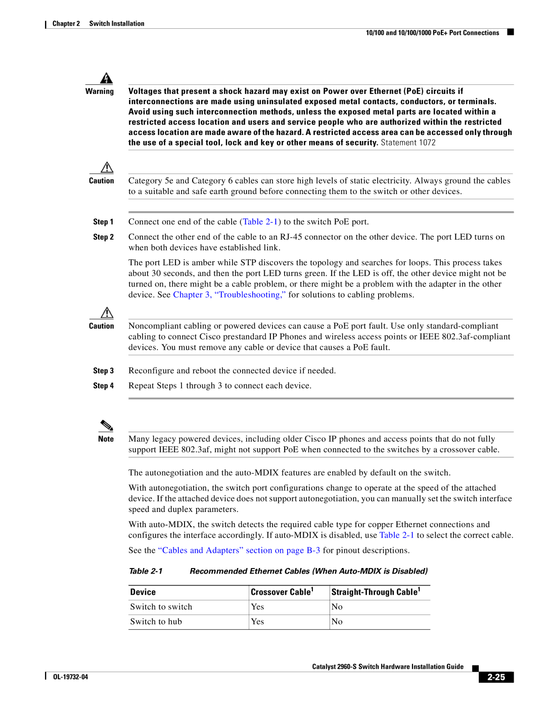
With auto-MDIX, the switch detects the required cable type for copper Ethernet connections and configures the interface accordingly. If auto-MDIX is disabled, use Table 2-1to select the correct cable.

See the “Cables and Adapters” section on page B-3for pinout descriptions.

Table 2-1 Recommended Ethernet Cables (When Auto-MDIX is Disabled)


Device

Crossover Cable1

Straight-Through Cable1


Switch to switch

Yes

No


Switch to hub

Yes

No


Catalyst 2960-S Switch Hardware Installation Guide


OL-19732-04


2-25


Page 55
Image 55
Cisco Systems 2960S-24TS-S, WSC2960S24TSSRF manual Device Crossover Cable1, Switch to switch Yes Switch to hub

2960S, WSC2960S24TSSRF, 2960S-24TS-S, 2960 specifications

Cisco Systems 2960 series switches are a prominent solution in the networking landscape, known for their reliability, scalability, and feature-rich offerings. Ideal for small to medium-sized enterprises, these switches provide a robust foundation for network infrastructure, ensuring optimal performance and connectivity.

One of the standout features of the Cisco 2960 series is its Layer 2 switching capabilities. The switches support multiple VLANs (Virtual Local Area Networks), allowing network administrators to segment traffic efficiently and enhance security protocols. This is crucial in modern networks where managing traffic and isolating sensitive information is a priority.

The Cisco 2960 series also incorporates advanced Quality of Service (QoS) features, enabling the prioritization of critical applications and services. This functionality ensures that time-sensitive data, such as voice and video traffic, maintains a high quality of service even in congested networks. With support for IEEE 802.1p and DSCP marking, administrators can fine-tune their network performance to meet specific organizational needs.

Power over Ethernet (PoE) is another significant characteristic of the Cisco 2960 series. This feature allows switches to deliver electrical power alongside data over Ethernet cables to devices such as IP phones, wireless access points, and surveillance cameras. With PoE, organizations can reduce clutter from power cables and increase deployment flexibility for various devices.

In terms of security, the Cisco 2960 series is equipped with a range of integrated security features. The switch supports port security, 802.1X authentication, and Access Control Lists (ACLs), providing robust defenses against unauthorized access and potential network vulnerabilities. These security measures are essential for protecting sensitive data and ensuring compliance with industry regulations.

Moreover, the Cisco 2960 series offers enhanced network management capabilities with Cisco's Intelligent Network Services. This includes support for Simple Network Management Protocol (SNMP), Cisco Prime, and Embedded Event Manager (EEM), allowing for efficient monitoring, troubleshooting, and policy enforcement across the network.

Additionally, the Cisco 2960 switches provide various models and configurations, catering to different networking needs. Options include models with varying port densities, uplink configurations, and stacking capabilities, making it easy for organizations to choose solutions that align perfectly with their requirements.

In summary, the Cisco 2960 series is a versatile and essential component of modern networking environments. Its advanced features, including Layer 2 support, QoS, PoE, robust security, and diverse management tools, make it an excellent choice for organizations looking to build a strong and secure network infrastructure.