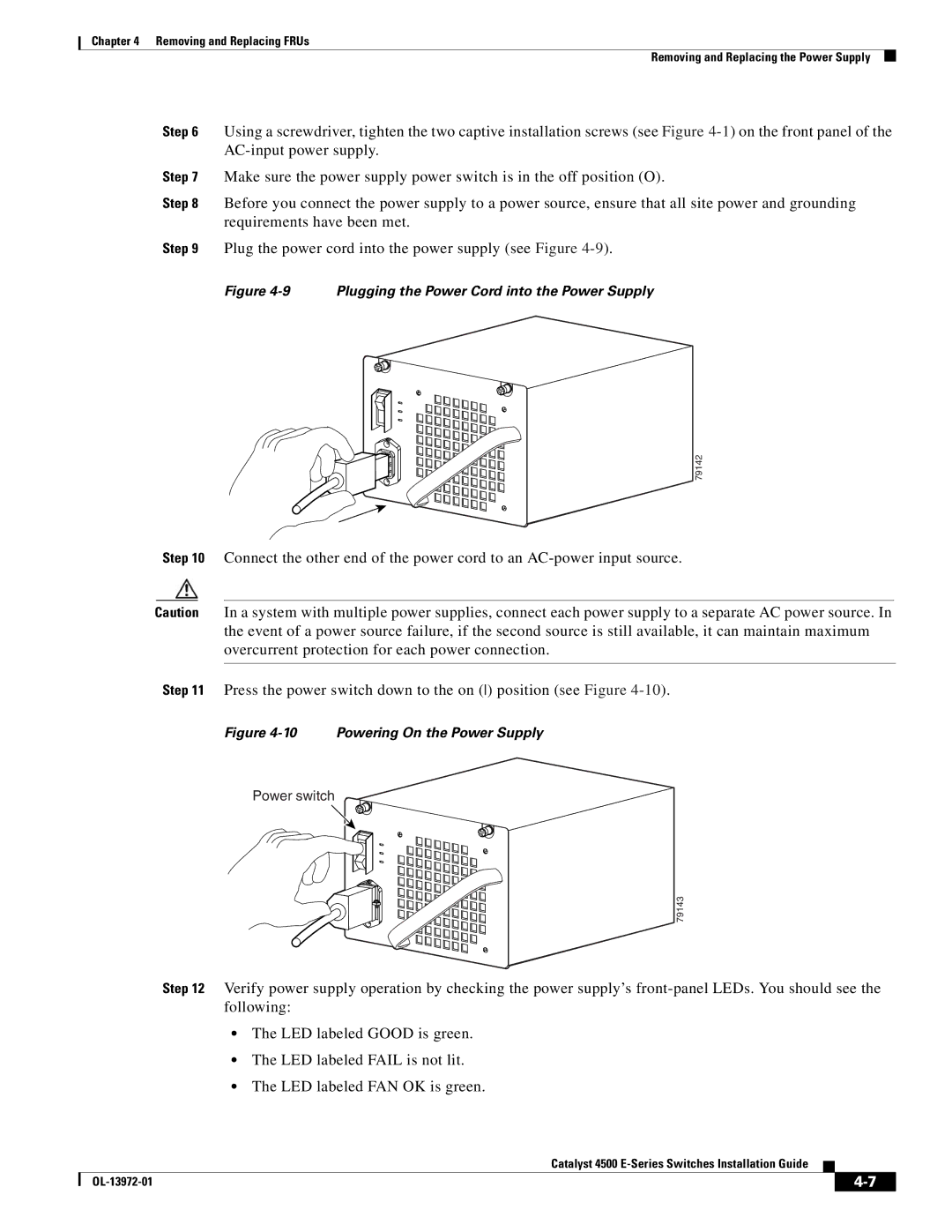
4500 E-Series, WSUPOE12VPSPL specifications
Cisco Systems has long been at the forefront of networking technology, consistently delivering innovative products that shape the future of digital communication. Among its extensive range of offerings, the WSUPOE12VPSPL and the Catalyst 4500 E-Series stand out as exemplary solutions tailored for businesses seeking robust, scalable, and versatile network infrastructure.The WSUPOE12VPSPL is a 12-port Power over Ethernet (PoE) switch that provides significant advantages for organizations looking to streamline their operations. It is designed to deliver power and data over a single cable, reducing the clutter of additional power supplies and cords. This efficiency not only simplifies deployment but also enhances the flexibility to place devices anywhere within the network environment, making it an ideal choice for powering IP phones, wireless access points, and surveillance cameras.
Main features of the WSUPOE12VPSPL include its ability to deliver up to 15.4 watts of power per port, supporting up to 12 PoE devices simultaneously. This capability is especially beneficial in environments where power outlets are scarce or where devices are located in non-traditional locations. With a rugged design suitable for various operational contexts, it ensures reliable performance even under demanding conditions.
When integrated within the Catalyst 4500 E-Series switches, organizations can leverage advanced technologies that enhance overall network performance and security. The Catalyst 4500 E-Series is known for its modularity, allowing businesses to expand their networks as required. Its architecture supports high throughput, advanced QoS features, and extensive Layer 2 and Layer 3 capabilities, ensuring efficient data handling and management.
Moreover, the Catalyst 4500 E-Series can integrate with Cisco’s digital network architecture and software-defined networking (SDN), facilitating automation and better visibility through tools such as Cisco DNA Center. This allows IT administrators to efficiently manage network resources, monitor performance, and implement security policies with ease.
In terms of operational intelligence, the integration with analytics tools enables organizations to gain insights into traffic patterns, user behaviors, and application performance, thus empowering data-driven decision-making.
Overall, the Cisco WSUPOE12VPSPL and the Catalyst 4500 E-Series offer a powerful combination of features, technologies, and characteristics that make them indispensable to modern networking. They cater to the demands of diverse business environments, ensuring reliability, flexibility, and scalability as organizations continue to evolve in an increasingly digital landscape.

