3
Installation and connection
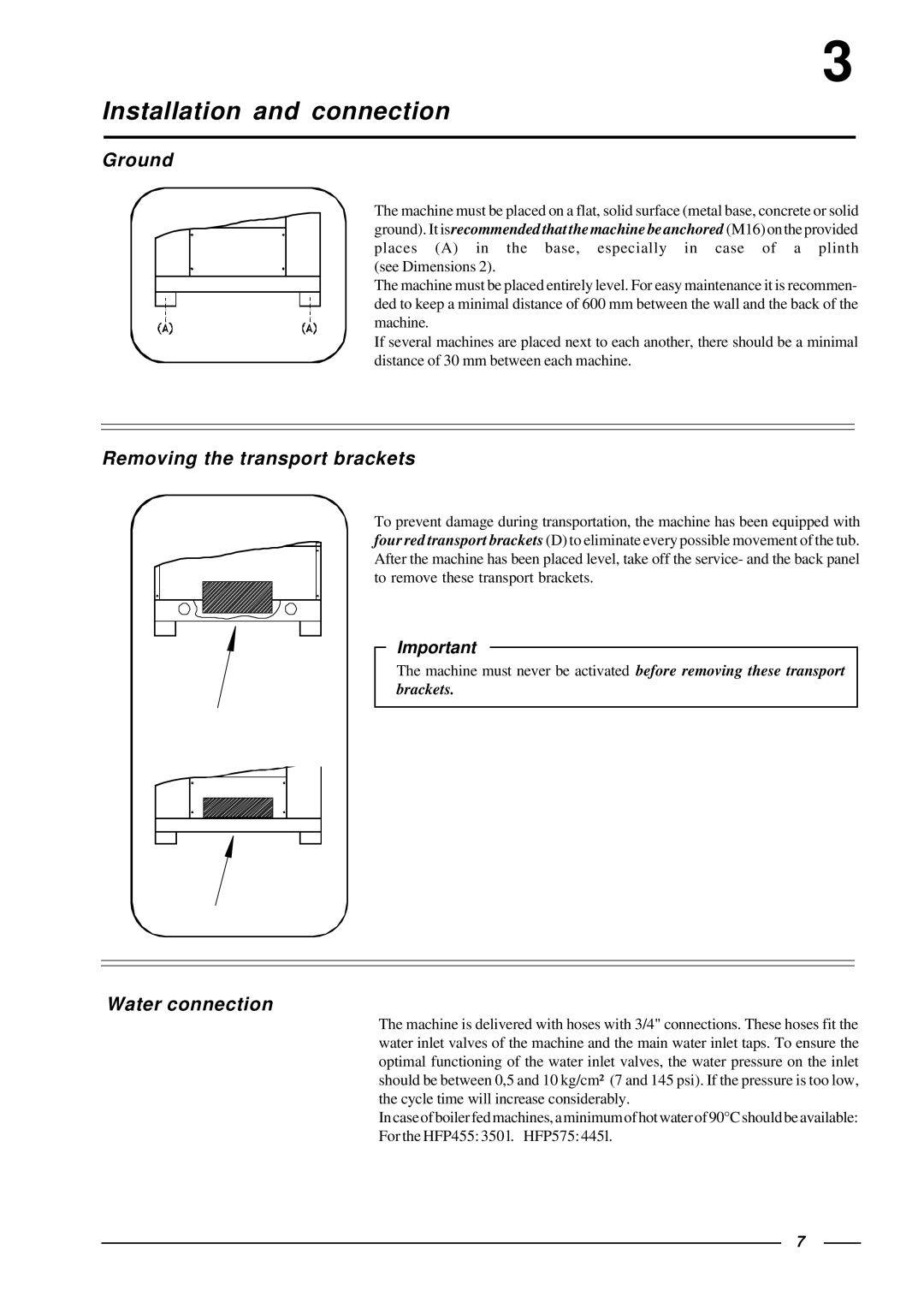
Ground
The machine must be placed on a flat, solid surface (metal base, concrete or solid ground). It isrecommended that the machine be anchored (M16) on the provided places (A) in the base, especially in case of a plinth (see Dimensions 2).
The machine must be placed entirely level. For easy maintenance it is recommen- ded to keep a minimal distance of 600 mm between the wall and the back of the machine.
If several machines are placed next to each another, there should be a minimal distance of 30 mm between each machine.
Removing the transport brackets
To prevent damage during transportation, the machine has been equipped with four red transport brackets (D) to eliminate every possible movement of the tub. After the machine has been placed level, take off the service- and the back panel to remove these transport brackets.
Important
The machine must never be activated before removing these transport brackets.
Water connection
The machine is delivered with hoses with 3/4" connections. These hoses fit the water inlet valves of the machine and the main water inlet taps. To ensure the optimal functioning of the water inlet valves, the water pressure on the inlet should be between 0,5 and 10 kg/cm² (7 and 145 psi). If the pressure is too low, the cycle time will increase considerably.
In case of boiler fed machines, a minimum of hot water of 90°C should be available: For the HFP455: 350 l. HFP575: 445l.
7