Manuals
/
CMA Dishmachines
/
Kitchen Appliance
/
Dishwasher
CMA Dishmachines
GL-X
owner manual
Maintenance, Timer assembly, Cam Adjustment
Models:
GL-X
1
11
19
19
Download
19 pages
36.39 Kb
8
9
10
11
12
13
14
15
Troubleshooting
Specifications
Install
Electrical Diagram
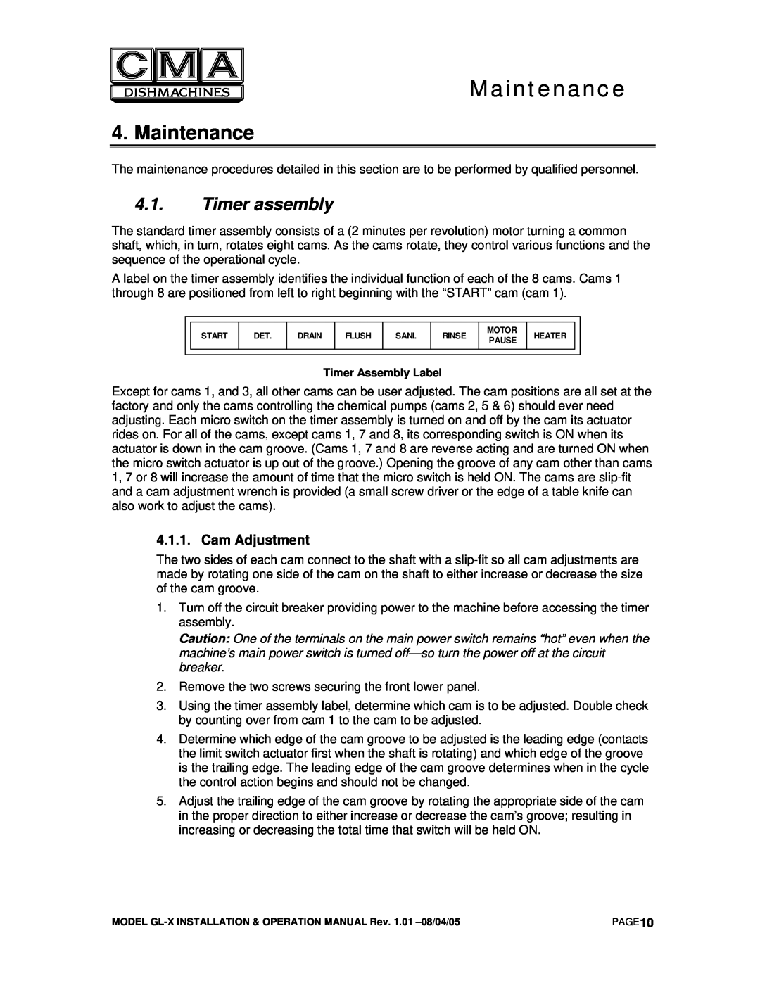
Timer assembly
Maintenance
Initial Setup
Page 11
Image 11
Page 10
Page 12
Page 11
Image 11
Page 10
Page 12
Contents
GARDEN GROVE, CALIFORNIA
Keep with machine for reference
C M A D I S H M A C H I N E S
1 2 7 0 0 K N O T T A V E N U E
MODEL CMA-GL-X
TABLE OF CONTENTS
SHIPPING WEIGHT
1. Specifications
GL-X
FRAME DIMENSIONS
RINSE
1.2.GL-XOperational Cycle
WASH
DRAIN
Page
2.1.Introduction to the GL-X
Getting Started
2. Getting Started
2.2.2. Plumbing
2.2.Receiving and Installation
Getting Started
2.2.1. Electrical
Glasswasher checked for concealed damage
3.2.General
3.1.Initial Setup
Operation
3.Operation
3.2.5. Pump Cavitation
Operation
3.2.3. Proper Filling
3.2.4. Water Pump
4.1.1. Cam Adjustment
Maintenance
4. Maintenance
4.1.Timer assembly
SOLUTION
Maintenance
4.2.Quick service guide
TECHNICAL ISSUE
4.3.Troubleshooting
Low heat during operation
Activating detergent primer
3.Chlorine sanitizer must be a minimum of 100 PPM
Addendum
Appendix A Operator & Cleaning Instructions
BOOSTER HEATER
6. Electrical Diagram
Electrical Diagram
WIRE DIAGRAM FOR MODEL GL-X
GROUND
WIRE DIAGRAM FOR MODEL GL-X
Rev.1.02
Top
Page
Image
Contents