Functional Block Diagram
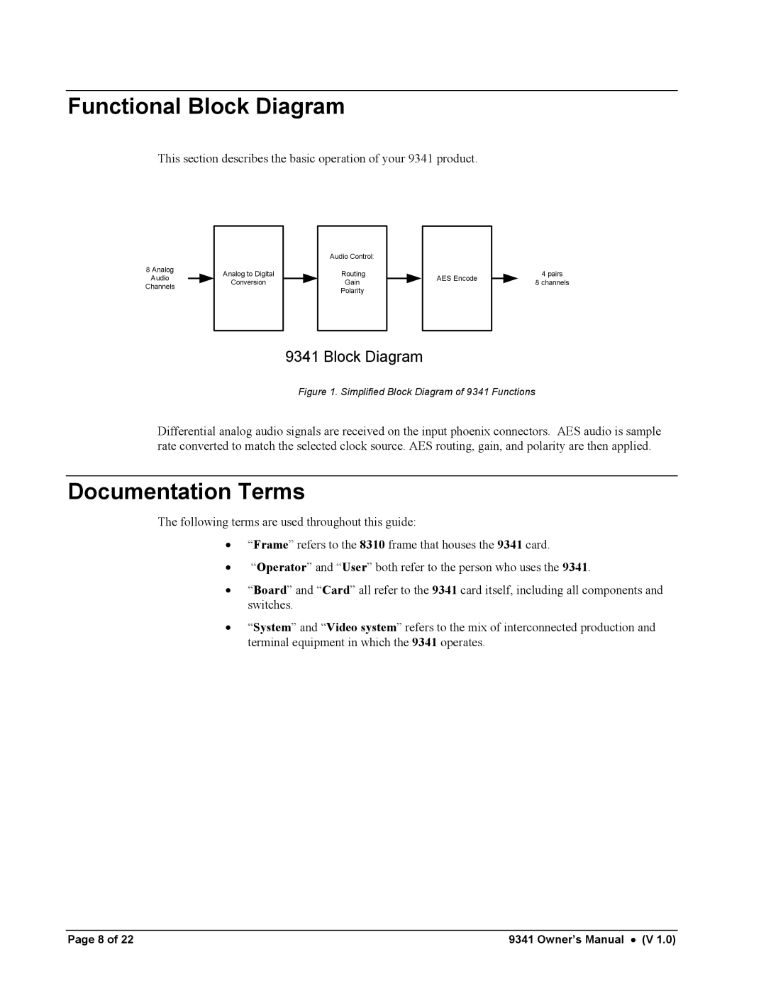
This section describes the basic operation of your 9341 product.
8 Analog
Audio
Channels
|
|
| Audio Control: |
|
|
|
|
Analog to Digital |
|
| Routing |
|
| AES Encode |
|
Conversion |
|
| Gain |
|
|
| |
|
|
|
|
|
| ||
|
|
| Polarity |
|
|
|
|
|
|
|
|
|
|
|
|
9341 Block Diagram
4pairs
8 channels
Figure 1. Simplified Block Diagram of 9341 Functions
Differential analog audio signals are received on the input phoenix connectors. AES audio is sample rate converted to match the selected clock source. AES routing, gain, and polarity are then applied.
Documentation Terms
The following terms are used throughout this guide:
•“Frame” refers to the 8310 frame that houses the 9341 card.
•“Operator” and “User” both refer to the person who uses the 9341.
•“Board” and “Card” all refer to the 9341 card itself, including all components and switches.
•“System” and “Video system” refers to the mix of interconnected production and terminal equipment in which the 9341 operates.
Page 8 of 22 | 9341 Owner’s Manual • (V 1.0) |
