Section I Introduction
FREQUENCY RANGE
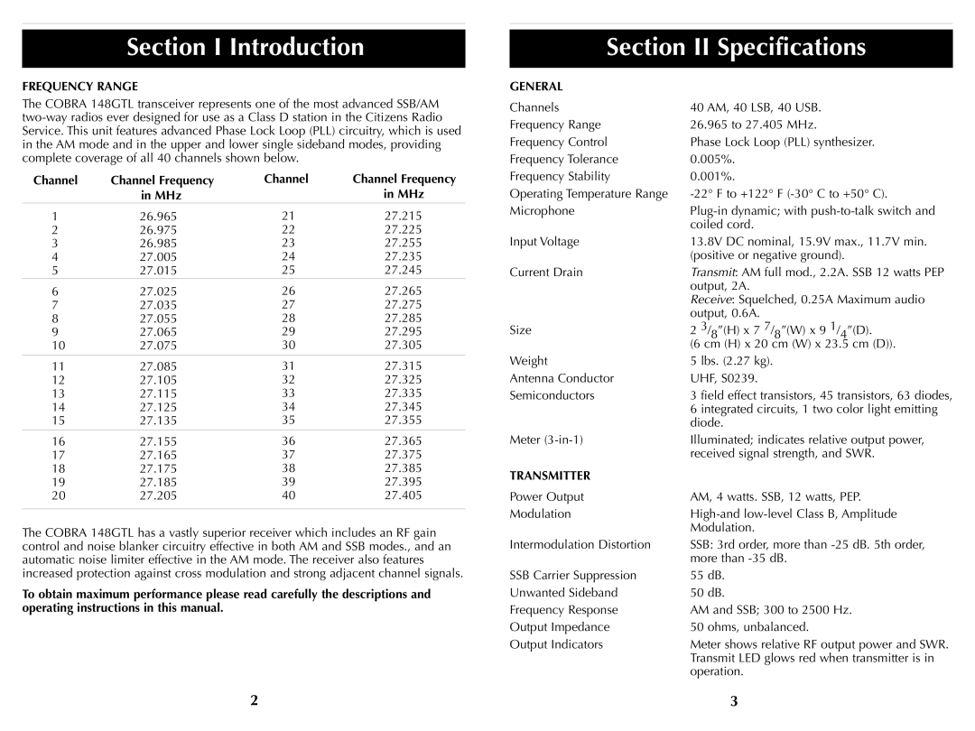
The COBRA 148GTL transceiver represents one of the most advanced SSB/AM
Channel | Channel Frequency | Channel | Channel Frequency |
| in MHz |
| in MHz |
1 | 26.965 | 21 | 27.215 |
2 | 26.975 | 22 | 27.225 |
3 | 26.985 | 23 | 27.255 |
4 | 27.005 | 24 | 27.235 |
5 | 27.015 | 25 | 27.245 |
6 | 27.025 | 26 | 27.265 |
7 | 27.035 | 27 | 27.275 |
8 | 27.055 | 28 | 27.285 |
9 | 27.065 | 29 | 27.295 |
10 | 27.075 | 30 | 27.305 |
|
|
|
|
11 | 27.085 | 31 | 27.315 |
12 | 27.105 | 32 | 27.325 |
13 | 27.115 | 33 | 27.335 |
14 | 27.125 | 34 | 27.345 |
15 | 27.135 | 35 | 27.355 |
16 | 27.155 | 36 | 27.365 |
17 | 27.165 | 37 | 27.375 |
18 | 27.175 | 38 | 27.385 |
19 | 27.185 | 39 | 27.395 |
20 | 27.205 | 40 | 27.405 |
|
|
|
|
The COBRA 148GTL has a vastly superior receiver which includes an RF gain control and noise blanker circuitry effective in both AM and SSB modes., and an automatic noise limiter effective in the AM mode. The receiver also features increased protection against cross modulation and strong adjacent channel signals.
To obtain maximum performance please read carefully the descriptions and operating instructions in this manual.
2
Section II Specifications
GENERAL |
|
|
|
|
|
Channels | 40 AM, 40 LSB, 40 USB. |
| |||
Frequency Range | 26.965 to 27.405 MHz. |
| |||
Frequency Control | Phase Lock Loop (PLL) synthesizer. | ||||
Frequency Tolerance | 0.005%. |
|
| ||
Frequency Stability | 0.001%. |
|
| ||
Operating Temperature Range | |||||
Microphone | |||||
| coiled cord. |
|
| ||
Input Voltage | 13.8V DC nominal, 15.9V max., 11.7V min. | ||||
| (positive or negative ground). | ||||
Current Drain | Transmit: AM full mod., 2.2A. SSB 12 watts PEP | ||||
| output, 2A. |
|
| ||
| Receive: Squelched, 0.25A Maximum audio | ||||
| output, 0.6A. |
|
| ||
Size | 2 3/ | 8 | ”(H) x 7 7/ | ”(W) x 9 | 1/ ”(D). |
|
|
| 8 | 4 | |
| (6 cm (H) x 20 cm (W) x 23.5 cm (D)). | ||||
Weight | 5 lbs. (2.27 kg). |
|
| ||
Antenna Conductor | UHF, S0239. |
|
| ||
Semiconductors | 3 field effect transistors, 45 transistors, 63 diodes, | ||||
| 6 integrated circuits, 1 two color light emitting | ||||
| diode. |
|
| ||
Meter | Illuminated; indicates relative output power, | ||||
| received signal strength, and SWR. | ||||
TRANSMITTER |
|
|
|
|
|
Power Output | AM, 4 watts. SSB, 12 watts, PEP. | ||||
Modulation | |||||
| Modulation. |
|
| ||
Intermodulation Distortion | SSB: 3rd order, more than | ||||
| more than |
| |||
SSB Carrier Suppression | 55 dB. |
|
| ||
Unwanted Sideband | 50 dB. |
|
| ||
Frequency Response | AM and SSB; 300 to 2500 Hz. | ||||
Output Impedance | 50 ohms, unbalanced. |
| |||
Output Indicators | Meter shows relative RF output power and SWR. | ||||
| Transmit LED glows red when transmitter is in | ||||
| operation. |
|
| ||
3
