Step
14
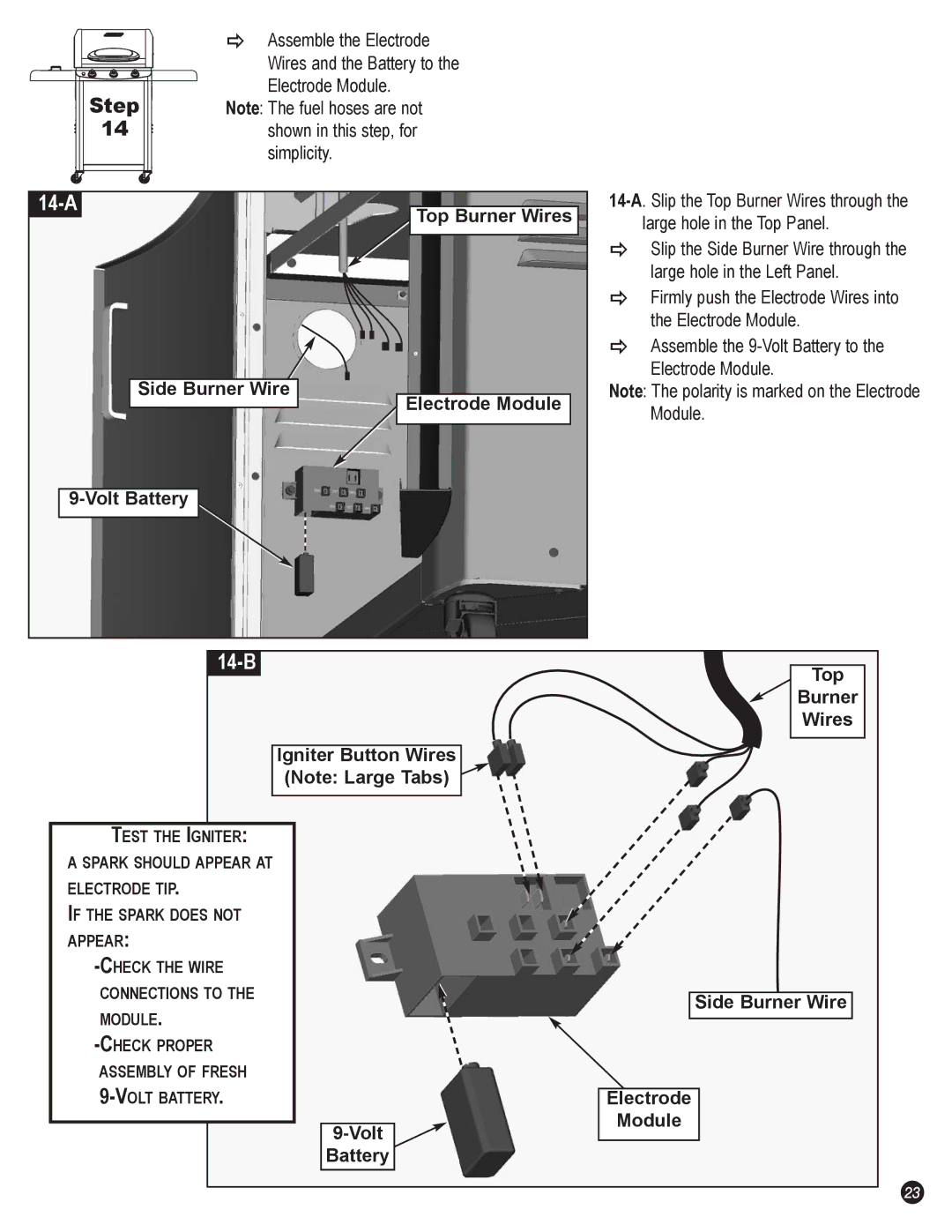
ÖAssemble the Electrode Wires and the Battery to the
Electrode Module. Note: The fuel hoses are not
shown in this step, for simplicity.
|
| Top Burner Wires | ||
|
|
| large hole in the Top Panel. | |
|
|
| Ö | Slip the Side Burner Wire through the |
|
|
|
| large hole in the Left Panel. |
|
|
| Ö | Firmly push the Electrode Wires into |
|
|
|
| the Electrode Module. |
|
|
| Ö | Assemble the |
| Side Burner Wire |
|
| Electrode Module. |
| Electrode Module | Note: The polarity is marked on the Electrode | ||
|
|
| Module. | |
|
|
|
| |
|
|
| ||
|
|
|
| Top |
|
|
|
| |
|
|
|
| Burner |
|
|
|
| Wires |
| Igniter Button Wires |
|
| |
| (Note: Large Tabs) |
|
| |
TEST THE IGNITER: |
|
|
|
|
|
|
A SPARK SHOULD APPEAR AT |
|
|
|
|
|
|
ELECTRODE TIP. |
|
|
|
|
|
|
IF THE SPARK DOES NOT |
|
|
|
|
|
|
APPEAR: |
|
|
|
|
|
|
|
|
|
|
|
| |
CONNECTIONS TO THE |
|
|
|
|
|
|
|
|
| Side Burner Wire | |||
MODULE. |
|
|
|
| ||
|
|
|
|
|
| |
|
|
|
|
|
| |
ASSEMBLY OF FRESH |
|
|
|
|
|
|
|
|
|
|
| ||
|
| Electrode |
| |||
|
|
|
| Module |
| |
|
|
|
| |||
|
|
|
|
|
| |
|
| Battery |
|
|
|
|
23