IntelliStripe 380
![]() 1.105
1.105 ![]()
![]() 5.789
5.789 ![]()
.546 | Mounting Screws |
| 1.616 |
| 3.230 |
Foot Pads (4) ![]()
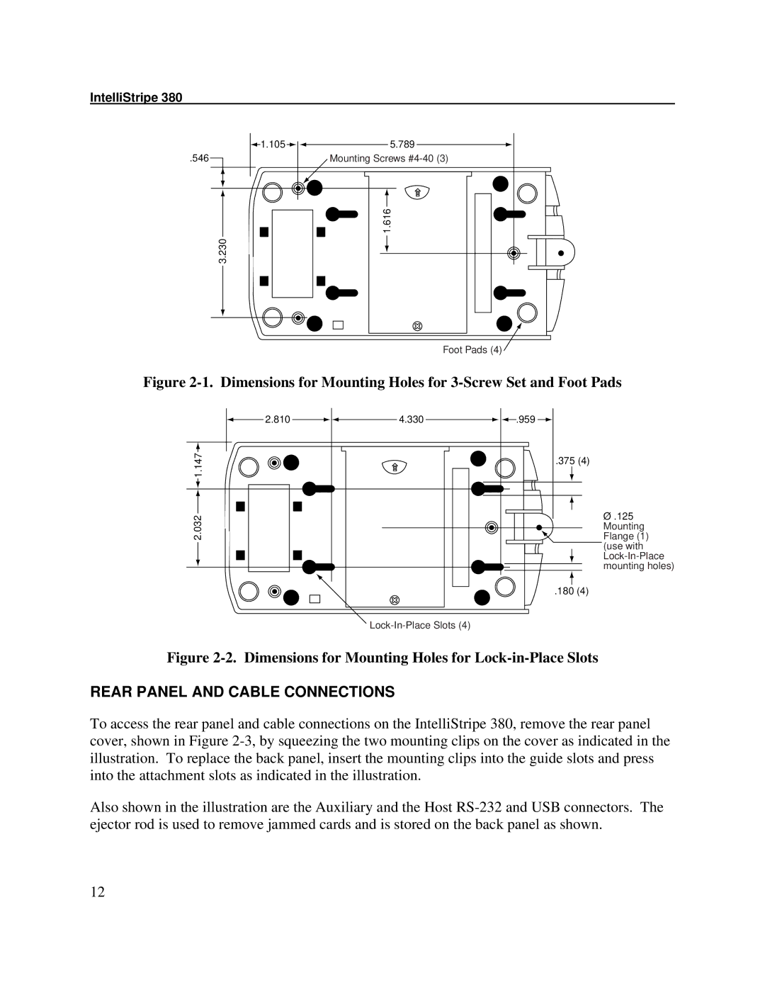
Figure 2-1. Dimensions for Mounting Holes for 3-Screw Set and Foot Pads
2.810 | 4.330 | .959 |
1.147 |
| .375 (4) |
|
| |
2.032 |
| Ø .125 |
| Flange (1) | |
|
| Mounting |
|
| (use with |
|
| |
|
| mounting holes) |
|
| .180 (4) |
Figure 2-2. Dimensions for Mounting Holes for Lock-in-Place Slots
REAR PANEL AND CABLE CONNECTIONS
To access the rear panel and cable connections on the IntelliStripe 380, remove the rear panel cover, shown in Figure
Also shown in the illustration are the Auxiliary and the Host
12