Maintenance and Service Guide
Page
Contents
Illustrated Parts Catalog
Screw Listing Index
Product Description
Key Description Options
Models
Key
Compaq Evo Notebook N410c Models
Nafta
N410c 120 Asia Pacific 470037-758
N410c 100 Asia Pacific 470040-136
N410c 100 Asia Pacific 470040-177
Compaq Evo Notebook N410c Models
Compaq Evo Notebook N400c Models
470013-752
470013-750
Features
Clearing a Password
Power Management
Component Function
Computer External Components
Front Panel Components
Right Side Components
Right Side Components
Connects the modem cable to an
Left Side Components
Left Side Components
Keyboard Components
Keyboard Components TouchPad Model
Keyboard Components
Keyboard Components
Fn key
Bottom Components
Bottom Components
Rear Panel Components
Rear Panel Components
Design Overview
Computer Setup Diagnostics Utilities
Troubleshooting
Using Computer Setup
Select To Do This
File Menu
Security Menu
Selecting from the Security Menu
Advanced Menu
Selecting from the Advanced Menu
Advanced Menu
Obtaining, Saving, or Printing Configuration Information
Using Compaq Diagnostics
Obtaining, Saving, or Printing Diagnostic Test Information
Maintenance and Service Guide
Flowchart Description
Troubleshooting Flowcharts
Troubleshooting Flowcharts Overview
All drives
Flowchart 2.1 Initial Troubleshooting
Flowchart 2.2 No Power, Part
Flowchart 2.3 No Power, Part
Internal
Flowchart 2.4 No Power, Part
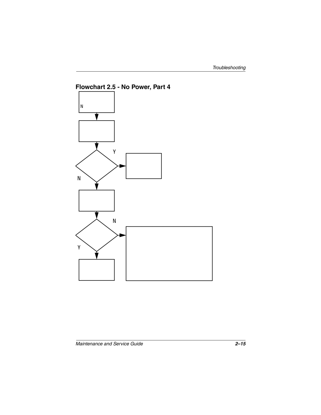
Flowchart 2.5 No Power, Part
Flowchart 2.6 No Video, Part
From Flowchart No Video, Part Remove
Flowchart 2.7 No Video, Part
Backplane board Switch box
Flowchart 2.8 Nonfunctioning Docking Station if applicable
No OS Loading
Flowchart 2.9 No Operating System OS Loading
CD?
Flowchart 2.10 No OS Loading from Hard Drive, Part
Flowchart 2.11 No OS Loading from Hard Drive, Part
Flowchart 2.12 No OS Loading from Hard Drive, Part
Flowchart 2.13 No OS Loading from Diskette Drive
Flowchart 2.14 No OS Loading from CD- or DVD-ROM Drive
Undock
Flowchart 2.15 No Audio, Part
Flowchart 2.16 No Audio, Part
Nonfunctioning Device Reseat
Flowchart 2.17 Nonfunctioning Device
Flowchart 2.18 Nonfunctioning Keyboard
Flowchart 2.19 Nonfunctioning Pointing Device
Flowchart 2.20 No Network or Modem Connection
Serial Number Location
Illustrated Parts Catalog
Computer System Major Components
Computer System Major Components
Palm rests
Computer System Major Components
Description Number Displays
Miscellaneous Plastics Kit
Computer System Major Components
Keyboard with pointing stick for use only with
Computer System Major Components
Base enclosures
Description Number Switch cover 231453-001 Hard drives
Spare Part
Computer System Major Components
Mini PCI communication boards
Battery packs
Description Number Modem cables
Miscellaneous Plastics Kit Components
Miscellaneous Plastics Kit Components
Miscellaneous Plastics Kit Components Spare Part Number
Mass Storage Devices
Mass Storage Devices
Optical drives
Mass Storage Devices
Description Number Hard drives
External diskette drive
Miscellaneous Spare Parts not illustrated
Miscellaneous Spare Parts
Description Number Mobile Expansion Units
RJ-11 P55 adapters
Description Number Modems
Modem adapters
Modem cable
Tools Required
Removal and Replacement Preliminaries
Plastic Parts
Service Considerations
Preventing Damage to Removable Drives
Preventing Electrostatic Damage
Packaging and Transporting Precautions
Workstation Precautions
Grounding Equipment and Methods
Material Use Voltage Protection Level
Typical Electrostatic Voltage Levels
Static-Shielding Materials
Relative Humidity Event 10% 40% 55%
Serial Number
Removal and Replacement Procedures
Section Description Removed
Disassembly Sequence Chart
Disassembly Sequence Chart
# of Screws
Removing the Primary Battery Pack
Preparing the Notebook for Disassembly
Removing the Optional External Battery Pack
Replacing the Computer Feet
Computer Feet
Palm Rest Spare Part Number Information
Palm Rest
Removing the Palm Rest Screws
Releasing the Palm Rest
Releasing the Palm Rest
Releasing the Palm Rest
Maintenance and Service Guide
10. Disconnecting the Pointing Stick Button Cable
Memory Expansion Board
11. Routing the RTC Battery and TouchPad Cables
12. Removing the Memory Expansion Compartment Cover
13. Removing a Memory Expansion Board
14. Removing a Memory Expansion Board
Hard Drive Spare Part Number Information
Hard Drive
Reverse the above procedure to install the hard drive
Mini PCI Communications Board Spare Part Number Information
Mini PCI Communications Board
Reverse the above procedure to install the modem/NIC board
Keyboard Spare Part Number Information
Keyboard
17. Removing the Keyboard Screws
18. Releasing the Keyboard
Reverse the above procedure to install the keyboard
20. Removing the RTC Battery
Real Time Clock RTC Battery
Switch Cover Spare Part Number Information
Switch Cover
Reverse the above procedure to install the switch cover
Display Spare Part Number Information
Display
23. Removing the Display
Removal and Replacement Procedures
Modem Cable Spare Part Number Information
Modem Cable
25. Removing the Right Display Support
26. Removing the Modem Cable on Evo Notebook N410c Models
27. Removing the Modem Cable on Evo Notebook N410c Models
Reverse the above procedure to install the modem cable
System Board Spare Part Number Information
System Board
29. Removing the Center Display Support
30. Removing the System Board Screw
31. Removing the System Board Screws and Screwlocks
Removal and Replacement Procedures
Maintenance and Service Guide
Removal and Replacement Procedures
Reverse the above procedure to install the system board
36. Installing the System Board
Maintenance and Service Guide
Computer
Vibration
Relative humidity
Shock
Inch XGA, TFT Display
Inch SVGA, TFT Display
Hard Drives
Speed Transfer rate
40 GB 30 GB 20 GB Physical configuration
Buffer size3
Disk rotational
Diskette Drive
CD-ROM Drive
Audio output level
DVD-ROM Drive
Track pitch
Environmental requirements
Battery Packs
Energy
Hardware DMA System Function
Power supply input
AC Adapter
System DMA
Hardware IRQ System Function
System Interrupts
System I/O Addresses
16F Unused
VGA
Size Memory Address System Function
System Memory Map
Table A-1 Parallel
Pin Signal
Table A-3 Stereo Speaker/Headphone
Pin Signal Audio out
Table A-2 Serial
Table A-5 Universal Serial Bus
Pin Signal Audio
Table A-4 Microphone
Table A-7 RJ-11 Modem
Table A-6 RJ-45 Network Interface
Table A-8 External Monitor
Conductor Power Cord Set
Power Cord Set Requirements
Country Accredited Agency Applicable Note Number
Conductor Power Cord Set Requirements
Country-Specific Requirements
BSI
Screw Listing
Head Color Qty Length Thread Width
Where used
Table C-1 Phillips P0 Metric 2.0 × 3.0 Screw
Figure C-2. TM2.0 × 6.0 Screw Locations
Table C-2 Torx T8 Metric 2.0 × 6.0 Screw
Figure C-3. TM2.0 × 6.0 Screw Locations
Figure C-4. TM2.0 × 6.0 Screw Locations
Head
Color Qty Length Thread Width Black Where used
Table C-3 Phillips P0 Metric 2.0 × 5.0 Screw
Figure C-6. TM2.0 × 4.0 Screw Location
Table C-4 Phillips P0 Metric 2.0 × 4.0 Screw
Figure C-7. TM2.0 × 4.0 Screw Location
Figure C-8. PM2.0 × 7.0 Barrel Screw Location
Table C-5 Phillips P0 Metric 2.0 × 7.0 Barrel Screw
Figure C-9. TM2.0 × 4.0 Screw Locations
Table C-5 Torx T8 Metric 2.0 × 4.0 Screw
Figure C-10. HM5.0 × 9.5 Screwlock Locations
Table C-6 Mm × 9.5 Screwlock
Index
Index
Index-3
Index-4
Index-5
Index-6