The Three-Layer Model
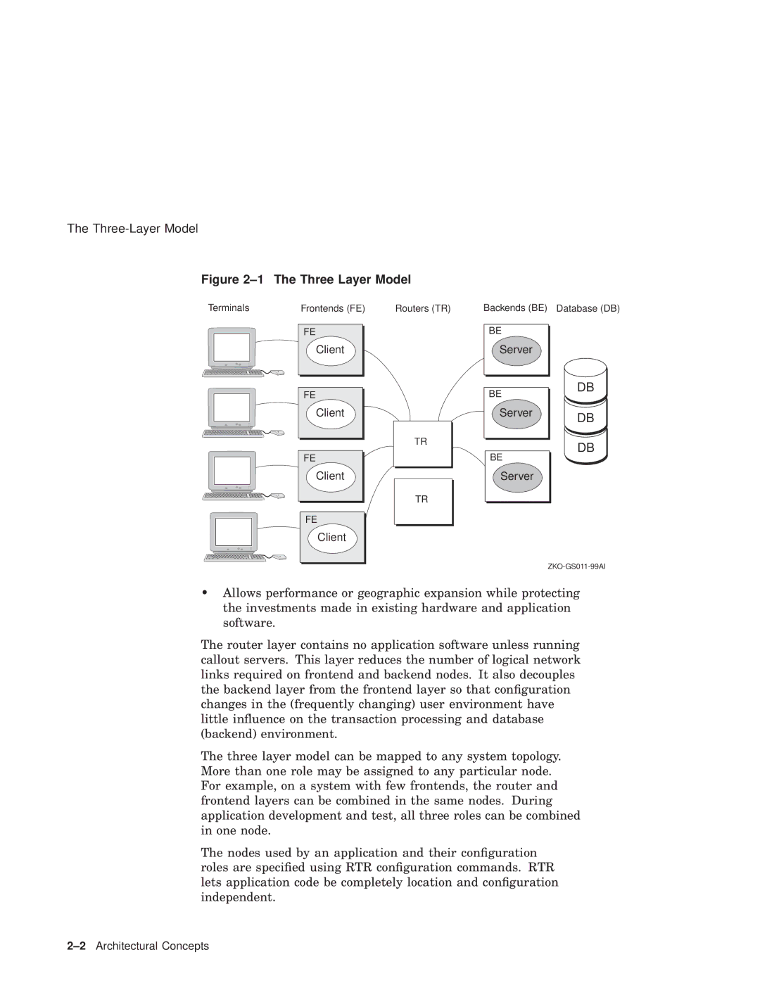
Figure 2–1 The Three Layer Model
Terminals | Frontends (FE) |
FE
Client
FE
Client
FE
Client
FE
Client
Routers (TR) | Backends (BE) Database (DB) | |
|
|
|
| BE |
|
| Server |
|
|
|
|
| BE | DB |
|
| |
| Server | DB |
|
| |
TR |
| DB |
| BE | |
|
| |
| Server |
|
TR |
|
|
•Allows performance or geographic expansion while protecting the investments made in existing hardware and application software.
The router layer contains no application software unless running callout servers. This layer reduces the number of logical network links required on frontend and backend nodes. It also decouples the backend layer from the frontend layer so that configuration changes in the (frequently changing) user environment have little influence on the transaction processing and database (backend) environment.
The three layer model can be mapped to any system topology. More than one role may be assigned to any particular node. For example, on a system with few frontends, the router and frontend layers can be combined in the same nodes. During application development and test, all three roles can be combined in one node.
The nodes used by an application and their configuration roles are specified using RTR configuration commands. RTR lets application code be completely location and configuration independent.
