RTR Terminology
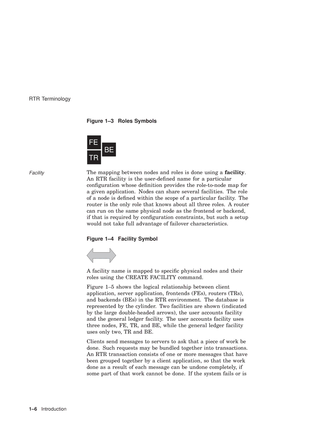
Figure 1–3 Roles Symbols
Facility | The mapping between nodes and roles is done using a facility. |
| An RTR facility is the user-defined name for a particular |
| configuration whose definition provides the role-to-node map for |
| a given application. Nodes can share several facilities. The role |
| of a node is defined within the scope of a particular facility. The |
| router is the only role that knows about all three roles. A router |
| can run on the same physical node as the frontend or backend, |
| if that is required by configuration constraints, but such a setup |
| would not take full advantage of failover characteristics. |
| Figure 1–4 Facility Symbol |
A facility name is mapped to specific physical nodes and their roles using the CREATE FACILITY command.
Figure 1–5 shows the logical relationship between client application, server application, frontends (FEs), routers (TRs), and backends (BEs) in the RTR environment. The database is represented by the cylinder. Two facilities are shown (indicated by the large double-headed arrows), the user accounts facility and the general ledger facility. The user accounts facility uses three nodes, FE, TR, and BE, while the general ledger facility uses only two, TR and BE.
Clients send messages to servers to ask that a piece of work be done. Such requests may be bundled together into transactions. An RTR transaction consists of one or more messages that have been grouped together by a client application, so that the work done as a result of each message can be undone completely, if some part of that work cannot be done. If the system fails or is

