Appendix A - Connector and Cable Pin Outs | 13 |
Appendix A - Connector and Cable Pin Outs
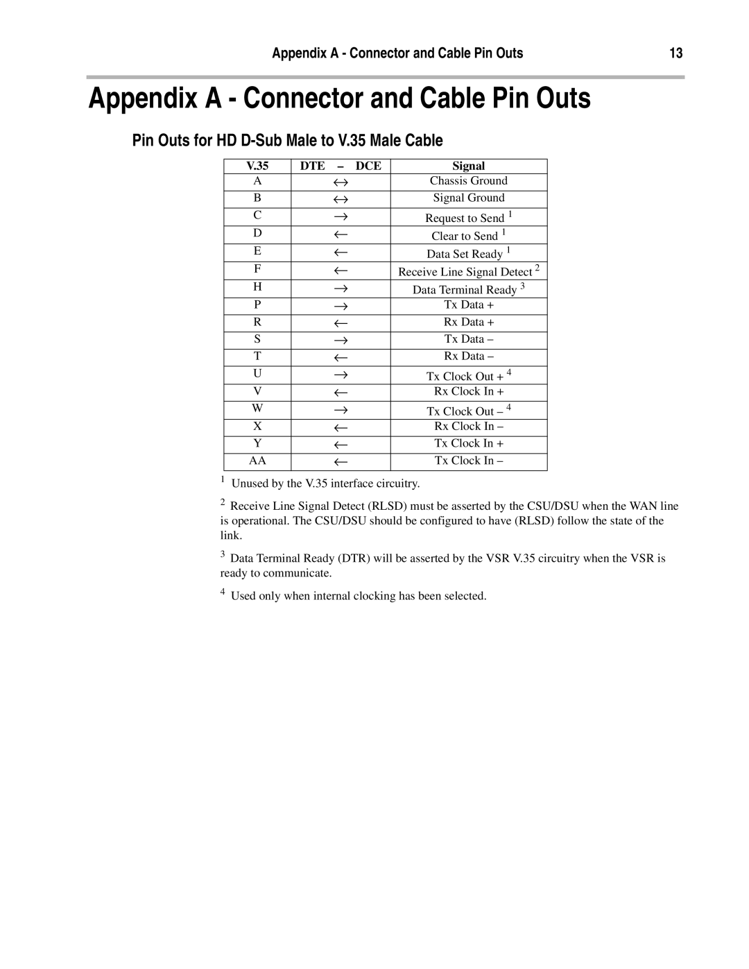
Pin Outs for HD D-Sub Male to V.35 Male Cable
V.35 | DTE – DCE | Signal |
A | ↔ | Chassis Ground |
B | ↔ | Signal Ground |
C | → | Request to Send 1 |
D | ← | Clear to Send 1 |
E | ← | Data Set Ready 1 |
F | ← | Receive Line Signal Detect 2 |
H | → | Data Terminal Ready 3 |
P | → | Tx Data + |
R | ← | Rx Data + |
S | → | Tx Data – |
T | ← | Rx Data – |
U | → | Tx Clock Out + 4 |
V | ← | Rx Clock In + |
W | → | Tx Clock Out – 4 |
X | ← | Rx Clock In – |
Y | ← | Tx Clock In + |
AA | ← | Tx Clock In – |
1Unused by the V.35 interface circuitry.
2Receive Line Signal Detect (RLSD) must be asserted by the CSU/DSU when the WAN line is operational. The CSU/DSU should be configured to have (RLSD) follow the state of the link.
3Data Terminal Ready (DTR) will be asserted by the VSR V.35 circuitry when the VSR is ready to communicate.
4Used only when internal clocking has been selected.
