Manuals
/
Continental
/
Household Appliance
/
Indoor Fireplace
Continental
BCDV42N, BCDV42P
manual
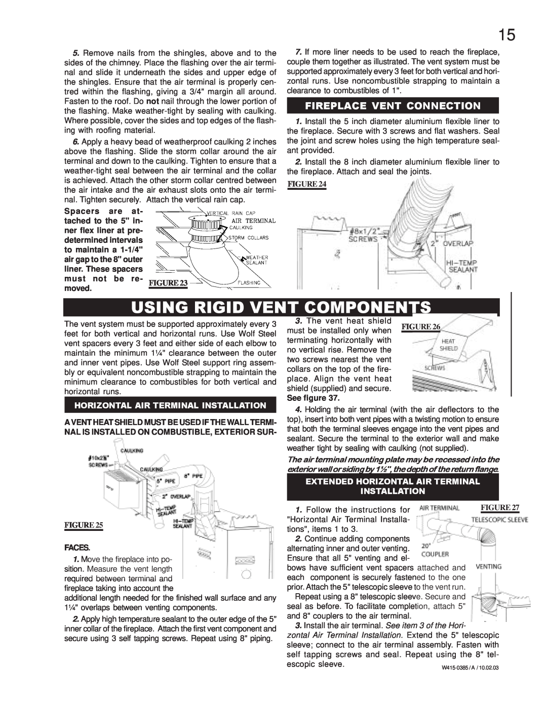
Using Rigid Vent Components, Fireplace Vent Connection
Models:
BCDV42N
BCDV42P
1
15
28
28
Download
28 pages
7.94 Kb
12
13
14
15
16
17
18
19
Troubleshooting
Install
Venting Application Flow Chart
Maintenance
Accessories
Do not kink flex connector
Adjustments
Logo Placement
Using Flexible Vent Components
Page 15
Image 15
Page 14
Page 16
Page 15
Image 15
Page 14
Page 16
Contents
DIRECT VENT MILLIVOLT SYSTEM
21 OPTIONAL BLOWER INSTALLATION
TABLE of CONTENTS
PLEASE RETAIN THIS MANUAL FOR FUTURE REFERENCE
13 - 18 INSTALLATION
CONDITIONS AND LIMITATIONS
CONTINENTAL GAS FIREPLACE PRESIDENTS LIFETIME LIMITED WARRANTY
Any labour related to warranty repair is not covered
ISO 9001 2000 Quality Assurance Certificate
GENERAL INSTRUCTIONS
GENERAL INFORMATION
CARE OF GLASS, AND PLATED PARTS
VENTING LENGTHS
VENTING
CANADIAN 12 INCHES 12 INCHES 12 INCHES 32 INCHES 32 INCHES 0 INCHES
AIR TERMINAL INSTALLATIONS
INSTALLATIONS
A B C D E F G H I J K L M N O
FIGURES 3 a-c
TYPICAL VENT INSTALLATIONS
SPECIAL VENT INSTALLATIONS
PERISCOPE TERMINATION
VENTING APPLICATION FLOW CHART
HORIZONTAL TERMINATION
VERTICAL TERMINATION
Formula 1 HT VT Formula 2 HT + VT 40 feet Example
HORIZONTAL TERMINATION
DEFINITIONS
ELBOW VENT LENGTH VALUES
Formula 1 HT 4.2 VT Formula 2 HT + VT 24.75 feet
Example
Formula 1 HT 4.2 VT
Formula 2 HT + VT 24.75 feet
VERTICAL TERMINATION
Formula 1 HT VT Formula 2 HT + VT 40 feet
FIGURE10
Formula 1 HT 3VT Formula 2 HT + VT 40 feet Example
REQUIRED VERTICAL RISE IN FEET VT
HORIZONTAL VENT RUN PLUS OFFSET IN FEET HT
INSTALLATION WALL AND CEILING PROTECTION
HORIZONTAL INSTALLATION
VERTICAL INSTALLATION
Use only approved aluminum flexible liner kits marked
USING FLEXIBLE VENT COMPONENTS
HORIZONTAL AIR TERMINAL INSTALLATION
VERTICAL AIR TERMINAL INSTALLATION
USING RIGID VENT COMPONENTS
EXTENDED HORIZONTAL AIR TERMINAL INSTALLATION
FIREPLACE VENT CONNECTION
1. Move the fireplace into position and secure using the
VERTICAL VENTING INSTALLATION
GAS INSTALLATION
Proceed once the vent installation is complete
MOBILE HOME INSTALLATION
FRAMING
FIGURES
NAILING
NAILING TAB INSTALLATION
MANTLE INSTALLATION
Additional set screws may be installed
PORCELAIN REFLECTIVE PANELS
FINISHING
L42 LOUVRE INSTALLATION
LOGO PLACEMENT
VERMICULITE
#2#3
LOG PLACEMENT
CHARCOAL EMBERS
B AC
OPTIONAL BLOWER INSTALLATION
OPTIONAL FAN INSTALLATION
GD36 THERMOSTATIC SENSOR CONTROL
To safely install the fan, turn off the electricity first
Turn off the gas and electrical power before servicing the fireplace
OPERATION / MAINTENANCE
MAINTENANCE
FOR YOUR SAFETY READ BEFORE LIGHTING
Air shutter adjustment must only be done by a qualified installer
ADJUSTMENTS
PILOT BURNER ADJUSTMENT
VENTURI ADJUSTMENT
GD420 5 FT
REPLACEMENTS
ACCESSORIES
REPLACEMENT PARTS
W415-0385 / A
TEST SOLUTION
TROUBLE SHOOTING GUIDE
SYMPTOM
PROBLEM
TOLI
Top
Page
Image
Contents