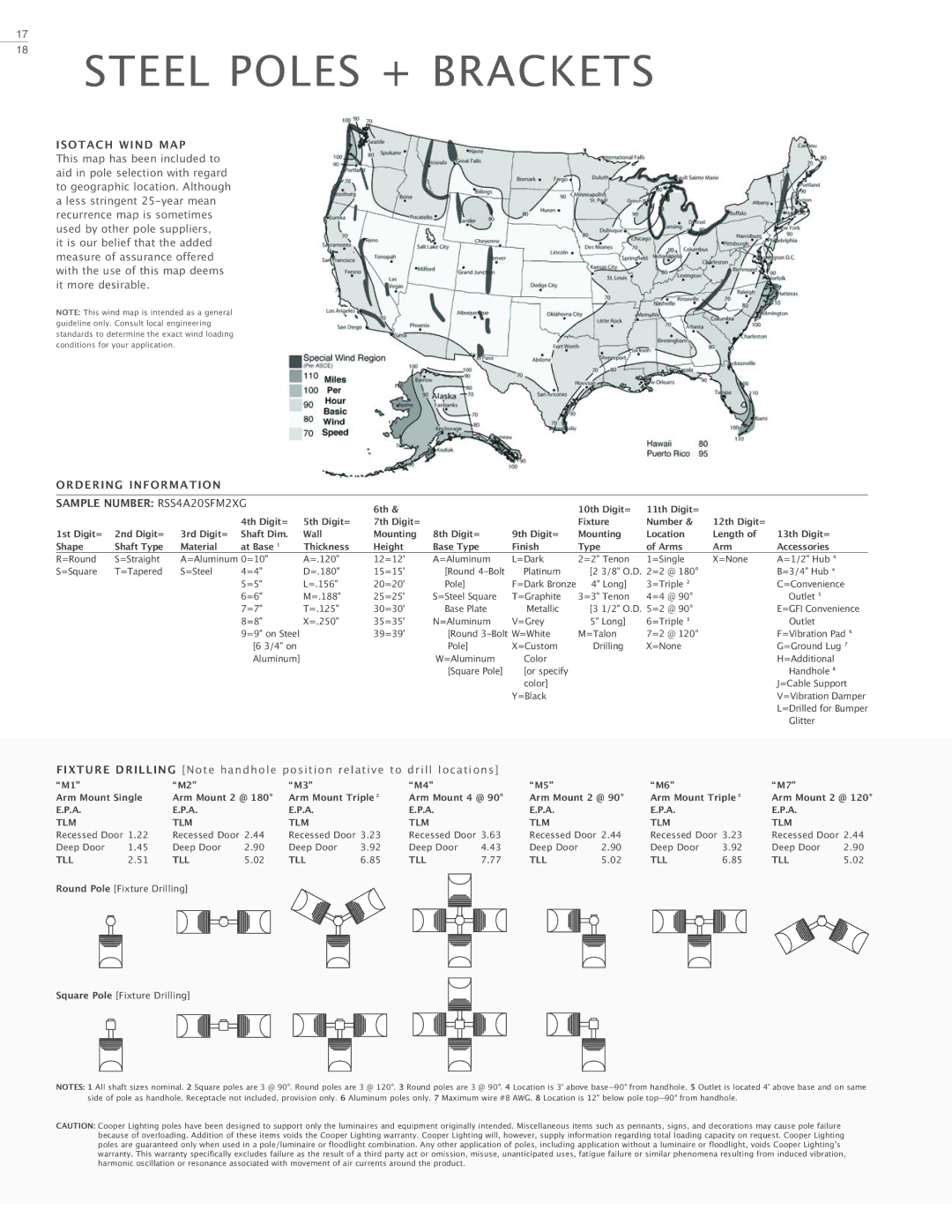
Architectural Area Luminaire specifications
Cooper Lighting's Architectural Area Luminaire represents a significant advancement in outdoor lighting technology, combining aesthetic appeal with cutting-edge functionality. Designed to illuminate public spaces, parks, roadways, and parking lots, this luminaire not only enhances visibility but also elevates the overall ambiance of its surroundings.One of the standout features of the Architectural Area Luminaire is its energy efficiency. Utilizing LED technology, the luminaire consumes significantly less energy compared to traditional lighting solutions. This not only leads to cost savings but also contributes to environmental sustainability by reducing carbon footprints. The high lumen output ensures bright and uniform lighting, which is particularly essential for outdoor areas where safety is a concern.
Durability is another key characteristic of this luminaire. Built with robust materials, the Architectural Area Luminaire is designed to withstand various weather conditions, making it ideal for both urban and rural settings. Its IP65 and above ratings ensure resistance to dust and water, providing reliable performance year-round. Furthermore, its rugged construction helps prevent vandalism and damage, ensuring longevity even in high-traffic areas.
Customization is a significant advantage of the Cooper Lighting Architectural Area Luminaire. It offers various mounting options and adjustable light distributions, allowing for tailored installations that meet specific project requirements. Additionally, the luminaire comes with multiple color temperature options, enabling designers to create specific lighting atmospheres that align with the character of the space being illuminated.
Smart technology integration is a notable aspect of modern Cooper Lighting products. The Architectural Area Luminaire can incorporate advanced controls such as dimming capabilities and adaptive lighting systems. These features not only enhance functionality but also allow for energy savings during off-peak hours.
In conclusion, Cooper Lighting's Architectural Area Luminaire is a remarkable solution for urban lighting needs, merging modern design with robust engineering. Its energy-efficient LEDs, durable materials, customizable options, and smart technology make it a standout choice for enhancing outdoor environments while prioritizing safety, sustainability, and aesthetics.

