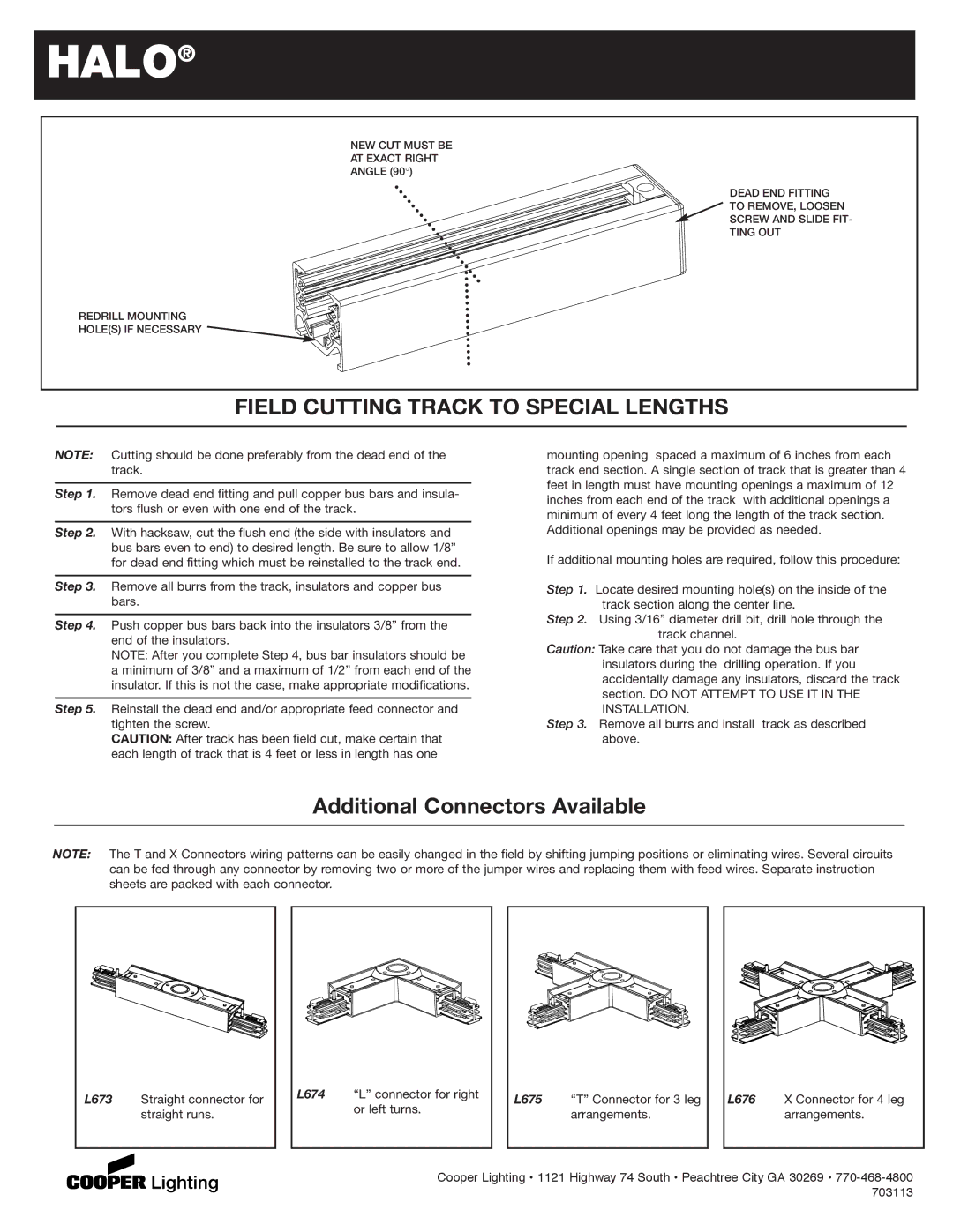
NEW CUT MUST BE

AT EXACT RIGHT

ANGLE (90°)

REDRILL MOUNTING

HOLE(S) IF NECESSARY

DEAD END FITTING TO REMOVE, LOOSEN SCREW AND SLIDE FIT- TING OUT

FIELD CUTTING TRACK TO SPECIAL LENGTHS

NOTE: Cutting should be done preferably from the dead end of the track.

Step 1. Remove dead end fitting and pull copper bus bars and insula- tors flush or even with one end of the track.

Step 2. With hacksaw, cut the flush end (the side with insulators and bus bars even to end) to desired length. Be sure to allow 1/8” for dead end fitting which must be reinstalled to the track end.

Step 3. Remove all burrs from the track, insulators and copper bus bars.

Step 4. Push copper bus bars back into the insulators 3/8” from the end of the insulators.

NOTE: After you complete Step 4, bus bar insulators should be a minimum of 3/8” and a maximum of 1/2” from each end of the insulator. If this is not the case, make appropriate modifications.

Step 5. Reinstall the dead end and/or appropriate feed connector and tighten the screw.

CAUTION: After track has been field cut, make certain that each length of track that is 4 feet or less in length has one

mounting opening spaced a maximum of 6 inches from each track end section. A single section of track that is greater than 4 feet in length must have mounting openings a maximum of 12 inches from each end of the track with additional openings a minimum of every 4 feet long the length of the track section. Additional openings may be provided as needed.

If additional mounting holes are required, follow this procedure:

Step 1. Locate desired mounting hole(s) on the inside of the track section along the center line.

Step 2. Using 3/16” diameter drill bit, drill hole through the track channel.

Caution: Take care that you do not damage the bus bar insulators during the drilling operation. If you accidentally damage any insulators, discard the track section. DO NOT ATTEMPT TO USE IT IN THE INSTALLATION.

Step 3. Remove all burrs and install track as described above.

Additional Connectors Available

NOTE: The T and X Connectors wiring patterns can be easily changed in the field by shifting jumping positions or eliminating wires. Several circuits can be fed through any connector by removing two or more of the jumper wires and replacing them with feed wires. Separate instruction sheets are packed with each connector.

L673

Straight connector for


straight runs.

L674

“L” connector for right


or left turns.

L675 “T” Connector for 3 leg arrangements.

L676 X Connector for 4 leg arrangements.

Cooper Lighting • 1121 Highway 74 South • Peachtree City GA 30269 • 770-468-4800 703113

Page 2
Image 2
Cooper Lighting L630 2C 2N Field Cutting Track to Special Lengths, Additional Connectors Available, L673, Straight runs

L630 2C 2N specifications

Cooper Lighting has long been a leader in the development of advanced lighting solutions, and the L630 2C 2N model exemplifies their commitment to innovation and performance. The L630 series is designed for both commercial and industrial applications, providing versatile and energy-efficient lighting options that meet the needs of various environments.

One of the main features of the Cooper Lighting L630 2C 2N is its superior energy efficiency. Utilizing the latest LED technology, this model significantly reduces energy consumption compared to traditional lighting systems. The longevity of LED lights means less frequent replacements, contributing to lower maintenance costs and minimal downtime in industrial settings. The L630 series has a remarkable lifespan, often exceeding 50,000 hours, making it a cost-effective solution for long-term use.

The L630 2C 2N also boasts a robust design, built to withstand the rigors of demanding environments. With a durable housing constructed from high-quality materials, this lighting solution is resistant to dust and moisture, making it ideal for warehouses, manufacturing plants, and outdoor spaces. Its design ensures reliable performance under various conditions, providing consistent light output where it’s needed most.

This model features versatile mounting options, allowing for easy installation in a variety of settings. Whether suspended from ceilings, wall-mounted, or used in modular configurations, the L630 2C 2N can be tailored to fit specific spatial constraints and lighting requirements. This adaptability makes it a popular choice among facility managers looking to optimize their lighting layouts.

In terms of technological advancements, the L630 series integrates smart lighting controls that enhance functionality and user experience. These controls support features like occupancy sensing and daylight harvesting, which automatically adjust lighting based on real-time conditions, further improving energy efficiency and user comfort.

Additionally, the L630 2C 2N offers excellent optical performance, providing uniform light distribution with minimal glare. This characteristic enhances visual comfort for those working or spending time in illuminated areas, promoting productivity and safety.

Overall, Cooper Lighting’s L630 2C 2N model combines energy efficiency, durability, versatility, and advanced technology, making it an exceptional choice for a wide range of lighting applications. Its thoughtful design and innovative features ensure that it meets the evolving needs of modern commercial and industrial spaces.