Installation | Step 10 | I |
| ||
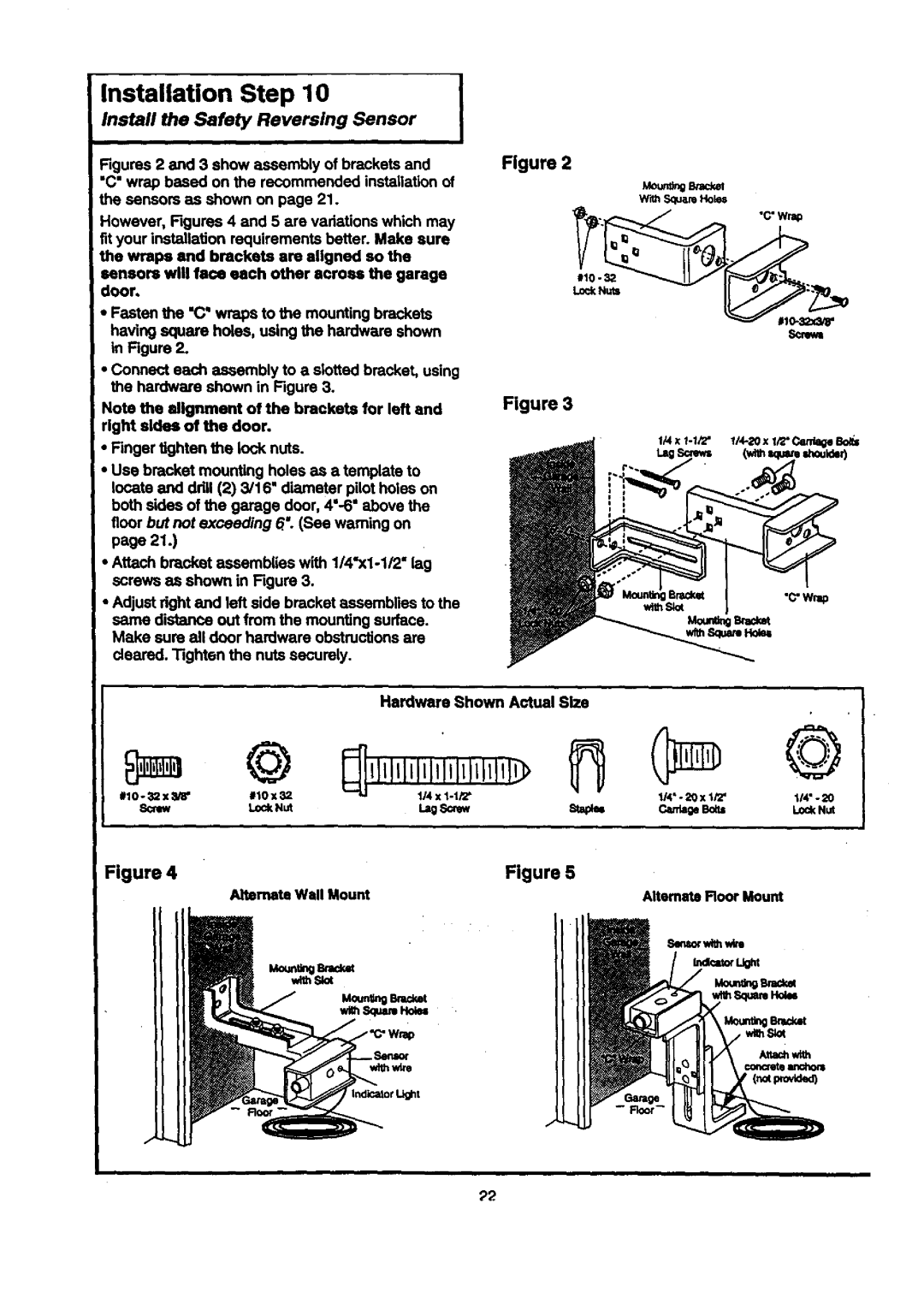
Install the Safety | Reversing Sensor |
|
'Figures 2 and 3 show assembly of brackets and
i "C" wrap based on the recommended installation of the sensors as shown on page 21.
However, Figures 4 and 5 are vadetions which may fit your installation requirements better. Make sure the wraps end brackets are aligned so the
sensors will face each other across the garage door,
•Fasten the "C" wraps to the mounting brackets having square holes, using the hardware shown in Figure 2.
•Connect each assembly to a slotted bracket, using the hardware shown in Figure 3.
Note the alignment of the brackets for left and right aides of the door.
•Finger tighten the lock nuts.
•Use bracket mounting holes as a template to locate and ddll (2) 3/16' diameter pilot holes on both sides of the garage door, 4"-6" above the floor but not exceeding 6: (See warning on page 21.)
•Attach bracket assemblies with 1/4"x1-1/2" lag screws as shown in Figure 3.
•Adjust dght and left side bracket assemblies to the same distance out from the mounting surface. Make sure all door hardware obstructions are dealed. Tighten the nuts securely.
Figure 2
Lo<:kNuts
Figure 3
Mo_ Brac_l W'dhSquareHoles
|
| Hardware Shown | Actual Size |
| © |
|
|
#10 o _12x :_gS" | #10x32 | Lag_ | St=paB |
SOtew | LockNut | ||
Figure 4 |
|
| Figure 5 |
| Alternate Wall Mount |
|
|
| withSlot |
|
|
©
114"- 20 x 1i'Z' | |
| LockNut |
Alternate Floor Mount
_2