INSTALLING THE
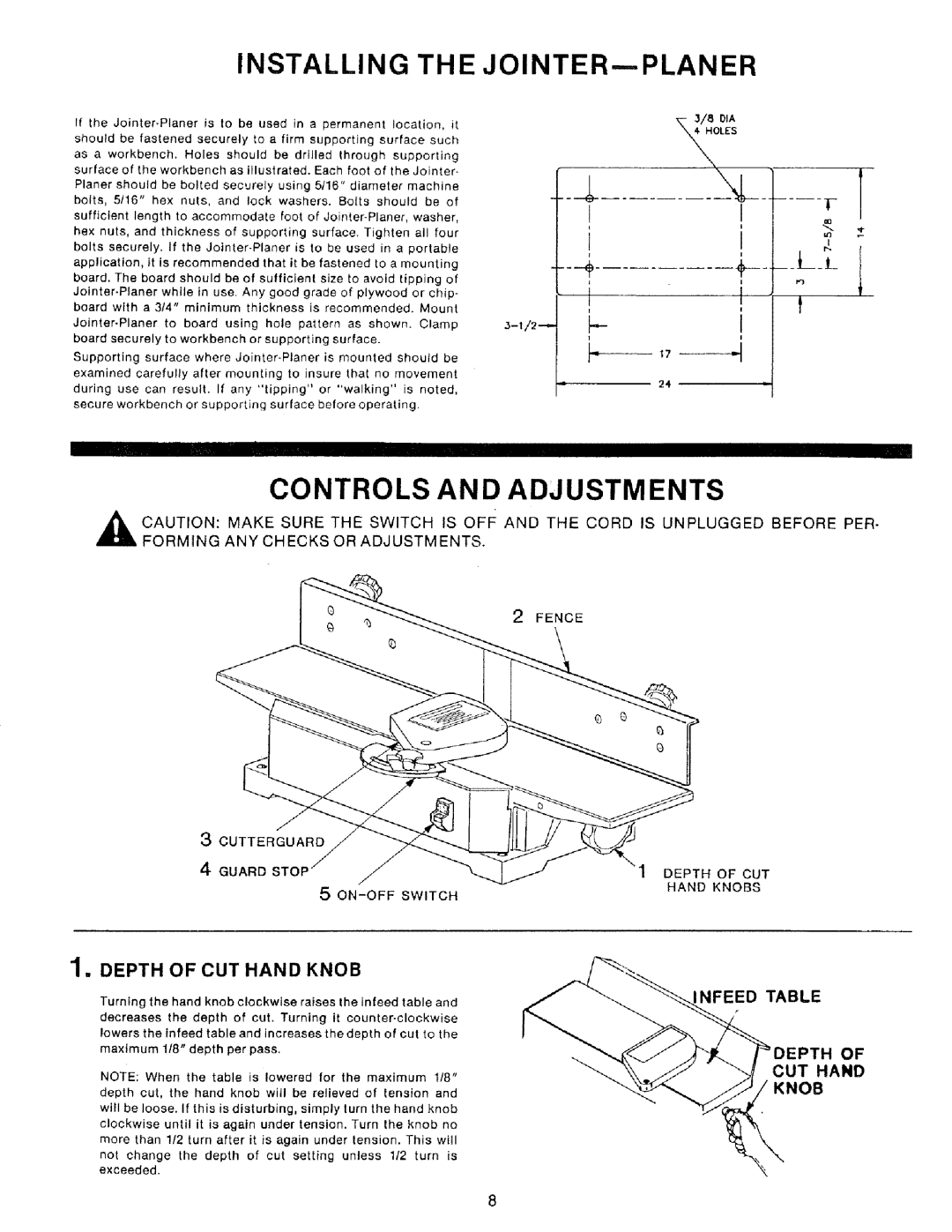
If the
as a workbench. Holes should be drilled through supporting surface of the workbench as illustrated. Each foot of the Jointer- Planer should be bolted securely using 5/16" diameter machine bolts, 5116" hex nuts, and lock washers. Bolts should be of
sufficient length to accommodate foot of
bolts securely. If the
application, it is recommended that it be fastened to a mounting board. The board should be of sufficient size to avoid tipping of
board with a 314" minimum thickness is recommended. Mount
Supporting surface where
during use can result. If any "tipping" or "walking" is noted, secure workbench or supporting surface before operating.
JOINTER--PLANER
_- 3/8 DIA
I!
_LL
J |
|
I | 1 |
i | |
i | |
| 24 |
T
,_ CAUTION: FORMING
I
CONTROLS AND ADJUSTMENTS
THE
MAKE SURE SWITCH IS oFF AND THE CORD IS UNPLUGGED BEFORE PER-
ANY CHECKS OR ADJUSTMENTS.
2FENCE
3 CUTTERGUARD
4 GUARD STOP
5 ON-OFF SWITCH
1. DEPTH OF CUT HAND KNOB
Turning the hand knob clockwise raises the infeed table and decreases the depth of cut. Turning it
NOTE: When the table is lowered for the maximum 118" depth cut, the hand knob will be relieved of tension and will be loose, If this is disturbing, simply turn the hand knob clockwise until it is again under tension. Turn the knob no more than 1/2 turn after it is again under tension. This will
not change the depth of cut setting unless 112 turn is exceeded.
1DEPTH OF CUT HAND KNOBS
NFEED TABLE
OF
CUT HAND
KNOB
