MAKINGA BEVELCROSSCUT
See Figures 40 - 41.
WARNING: Make sure the blade guard assembly
is installed and working properly to avoid possible serious injury.
A WARNING: The miter gauge must be on the left side of the blade to avoid trapping the wood and causing kickback and the risk of serious personal injury.
[] Remove the rip fence.
[] Unlock the bevel locking lever.
[] Adjust the bevel angle to the desired setting.
[] Lock the bevel locking lever.
[] Set the blade to the correct depth for the workpiece.
[] Set the miter gauge to 0° and tighten the lock knob.
[] Make sure the wood is clear of the blade before turning on the saw.
[] Turn the saw on.
[] Let the blade build up to full speed before moving the workpiece into the blade.
[] Hold the workpiece firmly with both hands on the miter gauge and feed the workpiece into the blade.
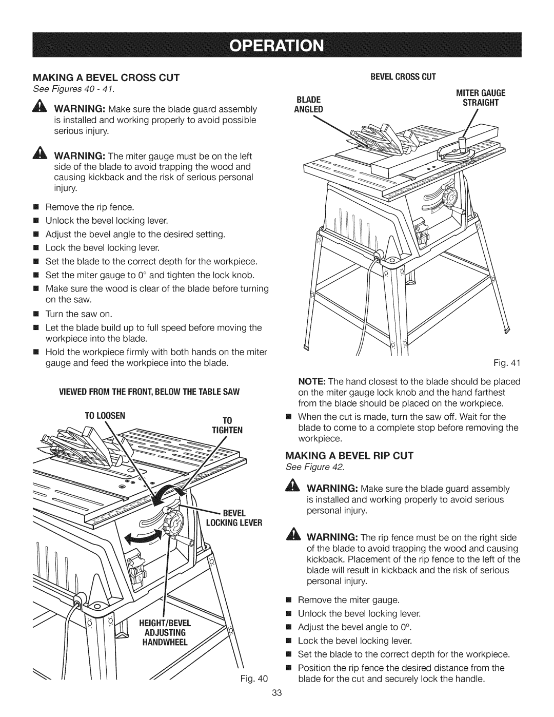
VIEWEDFROMTHEFRONT,BELOWTHETABLESAW
TOLOOSEN
TO
TIGHTEN
BEVEL
LOCKINGLEVER
Fig. 40
BEVELCROSSCUT
MITERGAUGE
BLADESTRAIGHT
ANGLED
Fig. 41
NOTE: The hand closest to the blade should be placed on the miter gauge lock knob and the hand farthest from the blade should be placed on the workpiece.
[] When the cut is made, turn the saw off. Wait for the blade to come to a complete stop before removing the workpiece.
MAKING A BEVEL RIP CUT
See Figure 42.
_I_ WARNING: Make sure the blade guard assembly is installed and working properly to avoid serious personal injury.
,aL WARNING: The rip fence must be on the right side of the blade to avoid trapping the wood and causing kickback. Placement of the rip fence to the left of the blade will result in kickback and the risk of serious personal injury.
[] Remove the miter gauge.
[] Unlock the bevel locking lever.
[] Adjust the bevel angle to 0°.
[] Lock the bevel locking lever.
[] Set the blade to the correct depth for the workpiece.
[] Position the rip fence the desired distance from the blade for the cut and securely lock the handle.
33