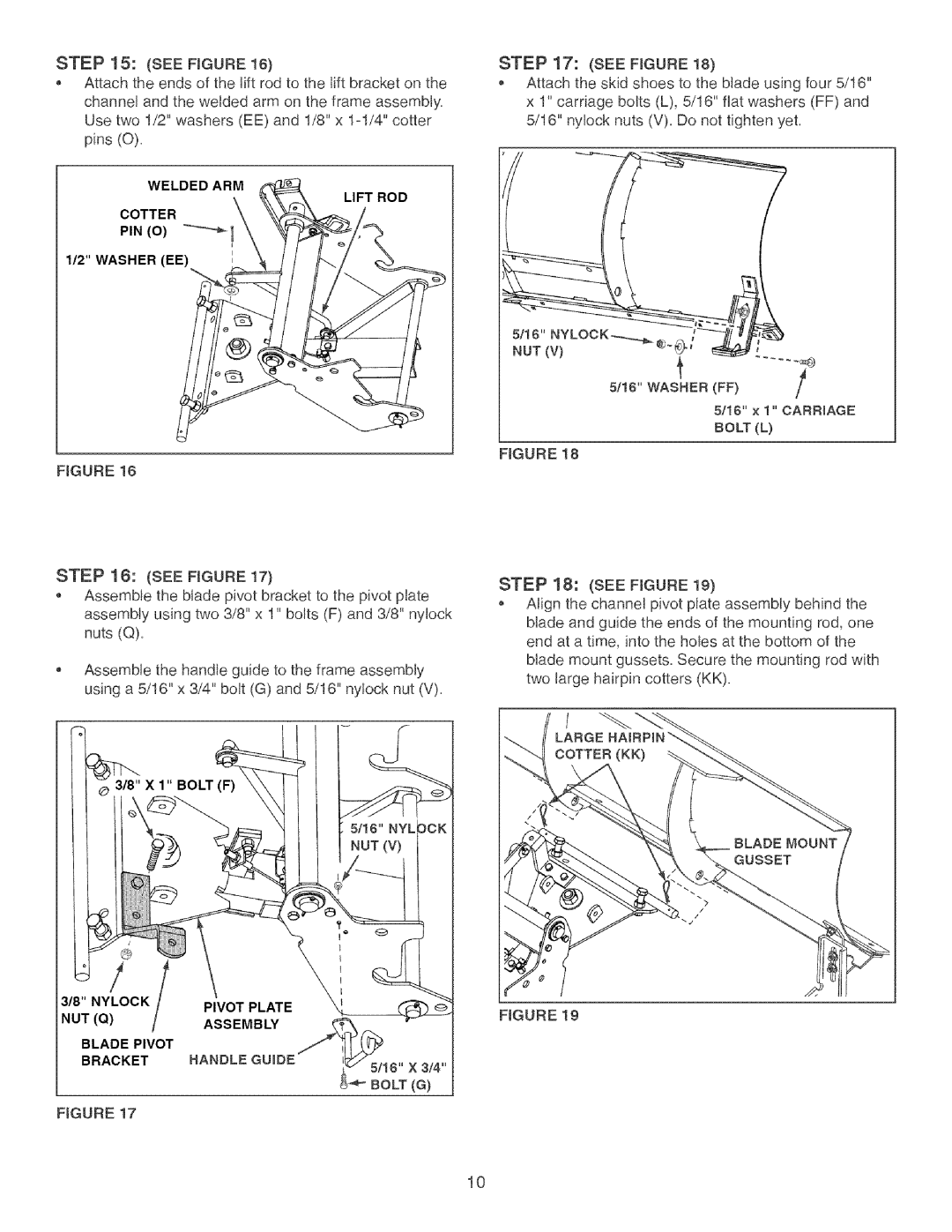
STEP 15: (SEE FIGURE 16)
,Attach the ends of the lift rod to the lift bracket on the channel and the welded arm on the frame assembly. Use two 1/2" washers (EE) and 1/8" x 1ol/4" cotter pins (O).
WELDED ARM
LIFT ROD
COTTER
PIN (0) _!
112" WASHER (EE) | 1 |
FIGURE 16
STEP 18: (SEE FIGURE 17)
,Assemble the blade pivot bracket to the pivot plate assembly using two 3/8" x 1" bolts (F) and 3/8" nylock nuts (Q),
Assemble the handle guide to the frame assembly using a 5/16" x 3/4" bolt (G) and 5/16" ny!ock nut (V),
3/8" NYLOOK | / | PIVOT PLATE |
NUT (Q) | / | ASSEMBLY |
BLADE PIVOT |
| |
BRACKET |
| HANDLE GUIDE |
|
| 5116" X 3/4" |
BOLT (G)
FIGURE 17
STEP 17: (SEE FIGURE 18)
,Attach the skid shoes to the blade using four 5/18" x 1" carriage bolts (L), 5/18" fiat washers (FF) and 5/18" nylock nuts (V), Do not tighten yet,
5116" x 1" CARRIAGE
BOLT (L)
FIGURE 18
STEP 18: (SEE FIGURE 19}
,Align the channel pivot plate assembly behind the blade and guide the ends of the mounting rod, one end at a time, into the holes at the bottom of the blade mount gussets. Secure the mounting rod with two large hairpin cotters (KK).
FIGURE 19
10