INSTALLING CLUTCH/IDLER ASSEMBLY
This section covers the installation of the Clutch/Idler assembly to tractors with attachment clutches that are either rod operated (p. 15), cable operated (p. 17) or electric (p. 19). Use the appropriate instructions for your tractor.
ROD OPERATED MANUAL ATTACHMENT CLUTCH
STEP 29: (SEE FIGURE 29)
•Move the attachment clutch lever on the dash panel to the disengaged (down) position.
•Screw the trunnion (II) onto the end of the snow thrower engagement rod.
•Locate the clutch arm (where the mower clutch rod was connected) underneath the right hand side the tractor, just to the inside of the suspension arm. If there is an extension attached to the clutch lever, the extension, bolt and nut must be removed and stored with the mower deck.
IMPORTANT:
•Position the engagement rod to the inside of the clutch arm and insert the drilled end of the rod through the arm. Secure with a 5/64" hairpin cotter (JJ).
| TRACTOR'S CLUTCH ARM |
| ENGAGEMENT ROD |
| TRUNNION (II) |
| SUSPENSION ARM |
| 5/64" HAIRPIN |
| COTTER (JJ) |
| REMOVE EXTENSION, |
| BOLT AND NUT |
| (IF PRESENT) |
FIGURE 29 | RIGHT SIDE VIEW |
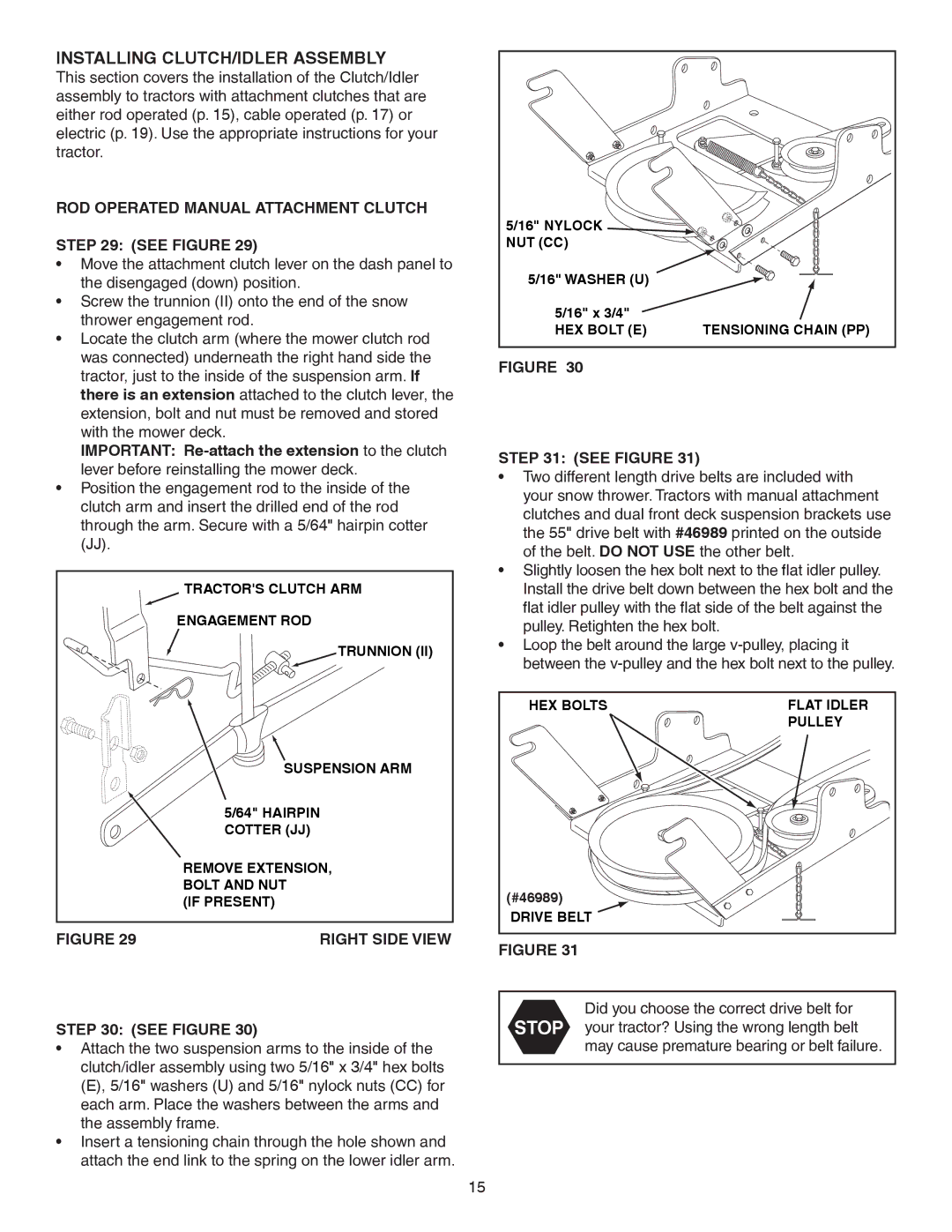
5/16" NYLOCK |
|
NUT (CC) |
|
5/16" WASHER (U) |
|
5/16" x 3/4" |
|
HEX BOLT (E) | TENSIONING CHAIN (PP) |
FIGURE 30
STEP 31: (SEE FIGURE 31)
•Two different length drive belts are included with your snow thrower. Tractors with manual attachment clutches and dual front deck suspension brackets use the 55" drive belt with #46989 printed on the outside of the belt. DO NOT USE the other belt.
•Slightly loosen the hex bolt next to the flat idler pulley. Install the drive belt down between the hex bolt and the flat idler pulley with the flat side of the belt against the pulley. Retighten the hex bolt.
•Loop the belt around the large
HEX BOLTS | FLAT IDLER |
| PULLEY |
(#46989) |
|
DRIVE BELT |
|
FIGURE 31
STEP 30: (SEE FIGURE 30)
•Attach the two suspension arms to the inside of the clutch/idler assembly using two 5/16" x 3/4" hex bolts (E), 5/16" washers (U) and 5/16" nylock nuts (CC) for each arm. Place the washers between the arms and the assembly frame.
•Insert a tensioning chain through the hole shown and attach the end link to the spring on the lower idler arm.
Did you choose the correct drive belt for STOP your tractor? Using the wrong length belt
may cause premature bearing or belt failure.
15