I | J | Hex Nut |
\Hinge
\
Step 1
Discharge
Chute
Wing
Knob
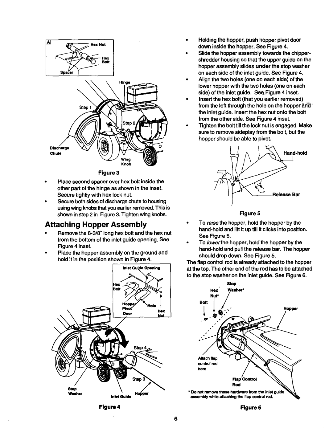
Figure 3
•Place second spacer over hex bolt inside the other part of the hinge as shown in the inset, Secure tightly with hex lock nut.
•Secure bothsides of discharge chute to housing using wing knobsthat you earlier removed. This is shown in step 2 in Figure 3. Tighten wing knobs.
Attaching Hopper Assembly
•Remove the
•Place the hopper assembly on the ground and hold it in the position shown in Figure 4.
Inlet Gu de Opening
0,
Stop
Washer
Inlet Guide
•Holding the hopper, push hopper pivot door down inside the hopper. See Figure 4.
•Slide the hopper assembly towards the chipper- shredder housing so that the upper guide on the hopper assembly slides under the stop washer on each side of the inlet guide. See Figure 4.
•Align the two holes (one on each side) of the lower hopper with the two holes (one on each side) of the inlet guide. See. Figure 4 inset.
•Insert the hex bolt (that you eadier removed) from the left through the hole on the hopper _n_ ° the inlet guide. Insert the hex nut onto the bolt from the other side. See Figure 4 inset.
•Tighten the bolt tillthe lock nut is engaged. Make sure to remove sideplay from the bolt, but the hopper should be able to pivot.
Figure 5
•To raise the hopper, hold the hopper by the
•To Iowerthe hopper, hold the hopper by the
The flap control rod is already attached to the hopper at the top. The other end of the rod has to be attached to the stop washer on the inlet guide. See Figure 6.
Stop .
He](' Washer*
Nut*
Bolt l
Hopper
Attach flap
control rod
hem
Fist
Rod
•Do not remove these hardware from the inletguide mmernblywhile attaching the flap control rod.
Figure 4 | Flgure6 |