Ikll II IIll
VICE AND
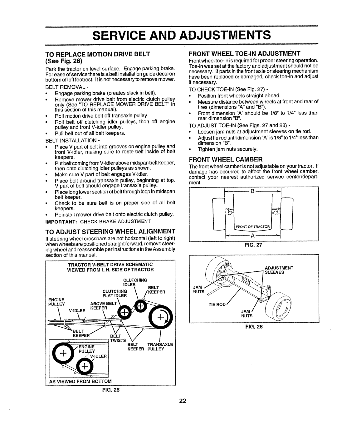
TO REPLACE MOTION DRIVE BELT (See Fig. 26)
Park the tractor on level surface_ Engage parking brake_ For ease ofservice there is a belt installationguide decal on bottom of left footrest. Itis not necessary to remove mower.
BELT REMOVAL -
°Engage parking brake (creates slack in belt).
°Remove mower'drive belt from electric clutch pulley
only (See 'q'OREPLACE MOWER DRIVE BELT" in this section of this manual)°
°Roll motion drive belt off transaxle pulley.
-Rol! belt off clutching idler pulleys, then off engine pulley and front Widler pulley,
•Pull belt out of all belt keepers.
BELT INSTALLATION -
•Place V part of belt into grooves on engine pulley and front
•Put belt coming from
°Make sure V part of belt engages
°Place belt around transaxle pulley, beginning at top.. V part of belt should engage transaxle pulley.,
•Place long lower section of belt through loop in midspan belt keeper_
•Check to be sure belt is on proper side of all bett keepers°
•Reinstall mower drive belt onto electric clutch puliey
IMPORTANT; CHECK BRAKE ADJUSTMENT
ADJUSTMENTS
FRONT WHEEL TOE-IN ADJUSTMENT
Frontwheel
TO CHECK
•Position front wheels straight ahead.
=Measure distance between wheels at front and rear of tires (dimensions "A" and "B").
=Front dimension "A" should be 1/8" to 1/4" Bessthan rear dimension "B'L
TO ADJUST
°Loosen jam nuts at adjustment sleeves on tie rod°
°Adjusttie rod until dimension "A" is 1/8"to 1/4" less than dimension "B"_
o Tighten jam nuts securely.
FRONT WHEEL CAMBER
The front wheel camber is not adjustable on your tractor_ If damage has occurred to affect the front wheel camber, contact your nearest authorized service center/depart- ment.
TO ADJUST STEERING WHEEL ALIGNMENT
If steering wheel crossbars are not horizontal (left to right) | FIG, 27 | |||
when wheels are positioned straight forward, remove steer- | ||||
ing wheel and reassemble per instructionsin the Assembly |
| |||
section of this manual. |
|
|
| |
| TRACTOR | ADJUSTMENT | ||
| VIEWED FROM LH. SIDE OF TRACTOR | |||
| SLEEVES | |||
|
|
|
| |
| CLUTCHING |
|
| |
| IDLER |
| JAM | |
| CLUTCHING |
| BELT | |
| \ | NUTS | ||
| FLAT IDLER |
| EEPER |
|
ENGINE |
|
|
| |
ABOVE |
|
|
| |
PULLEY |
|
| TIE ROD | |
|
|
|
| |
|
|
|
| NUTS |
FIG, 28
BE_'
KEEPERBELT
TWISTS
BELT TRANSAXLE
KEEPER PULLEY
AS VIEWED FROM BOTTOM
FIG, 26
22