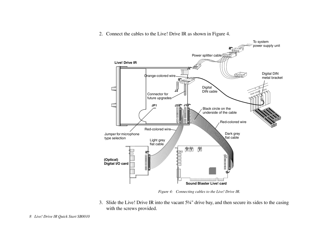
2. Connect the cables to the Live! Drive IR as shown in Figure 4.
|
|
| To system |
|
|
| power supply unit |
|
|
| Power splitter cable |
Live! Drive IR |
|
|
|
| Digital DIN | ||
| metal bracket | ||
|
|
| |
|
| J3 | Digital |
| Connector for | DIN cable | |
|
|
| |
| future upgrades |
|
|
| JP1 | J2 | J1 |
|
|
| Black circle on the |
|
|
| underside of the cable |
|
|
| |
|
|
| |
Jumper for microphone |
|
| Dark grey |
type selection | Light grey |
| flat cable |
|
|
| |
flat cable
(Optical) Digital I/O card
Sound Blaster Live! card
Figure 4: Connecting cables to the Live! Drive IR.
3.Slide the Live! Drive IR into the vacant 5¼" drive bay, and then secure its sides to the casing with the screws provided.
8 Live! Drive IR Quick Start SB0010