Contents
18R / X 20R
Page
Important Precautions
Page
Important Safety Instructions
Wichtige Sicherheitshinweise
Instructions Importantes De Securite
Instrucciones Importantes Para Su Seguridad
Table Of Contents
18R/20R Block Diagram
How To Use This Manual
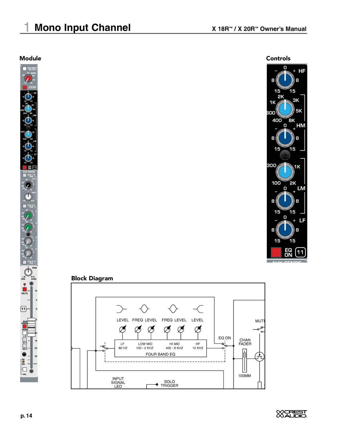
Mono Input Channel
Gain
Lo Cut Switch
Line Input Mic Pad
Hz Lo-Cut Filter
Mono Input Channel
Low Mid-LM
High Frequency-HF
High Mid-HM
Low Frequency-LF
Module Block Diagram Controls
Aux Sends 3, 4, 5
Aux 1 2 PRE
Aux Sends 1
AUX 3-4 PRE
Mono Input Channel
Mute
PFL
Rear Panel
XLR Mic Input Jack
48V Phantom Power
Line Input Jack
Chan Insert Jack
Stereo Input Channel
Str Line In Mic Pad
SUM Inputs
Module
Front Panel Features Stereo EQ
Low Frequency-LM
Stereo Input Channel
AUX 5 and AUX 6 are post-fader AUX 5 and AUX 6 are pre-fader
Stereo Input Channel
BAL Control
Input Fader
Rear Panel Block Diagram
+48V On
Master Section
Tape
Solo OFF
From Monitor
Master Section
Solo LED
PWR LED
Master Section
AUX OUT 3, 4, 5 & 6 Level Control
AUX OUT 1-2 Level Control
Aux 1-2 AFL
Aux 3, 4, 5, & 6 AFL
Master section
Mono assignments for Groups 1, 2, 3
GroupPK / SIG LED Indicators
GROUPAssignment Section
Left Assignments For Groups 1, 2, 3
Block Diagram Controls
SUM Mono
Monitor Output Section
Monitor Level Control
Module Block Diagram Controls
Source Select
Mono
Master Section
Mono AFL
Mono PK/SIG LED
Left/Right PK/SIG LED
MONO, Left & Right Master faders 100mm
Master Section
Insert For Left, Right and Mono
Left, Right and Mono Bus Inputs
Group 1, 2, 3 & 4 Bus Inputs
Left, Right And Mono Main Outputs
Rear Panel Block Diagram
Aux OUT XLRs 1Thru
Aux Insert 1Thru
Aux Outtrs Jacks 1Thru
Group Inserts 1Thru
Master Section
Monitor Out
Tape Line
Alt Out
Solo Link
Specifications
Connector Pinout Detail
18R/20R Internal Options
User Notes
User Notes
Crest P/N