• 1/4” TRS Insert •
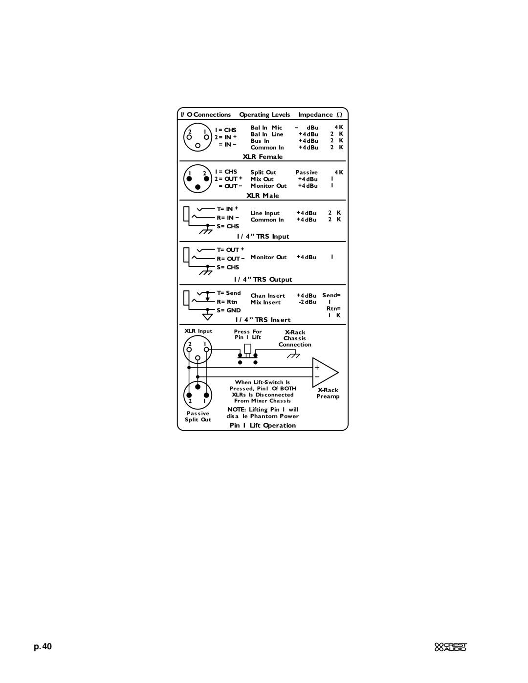
I/O Connections • Operating Levels • Impedance (Ω)
2 1 1= CHS
32= IN + 3= IN –
Bal In (Mic) | 4K | |
Bal In (Line) | +4dBu | 20K |
Bus In | +4dBu | 20K |
Common In | +4dBu | 20K |
• XLR Female •
1 2 1= CHS | Split Out | Passive | 4K | ||
3 | 2= OUT + | Mix Out | +4dBu | 100 | |
3= OUT – | Monitor Out | +4dBu | 100 | ||
| |||||
| • XLR Male • |
|
| ||
| T= IN + | Line Input | +4dBu | 20K | |
| R= IN – | ||||
| Common In | +4dBu | 20K | ||
| S= CHS |
|
|
| |
| • 1/4” TRS Input • |
|
| ||
| T= OUT + | Monitor Out | +4dBu | 100 | |
| R= OUT – | ||||
| S= CHS |
|
|
| |
| • 1/4” TRS Output • |
| |||
| T= Send | Chan Insert | +4dBu | Send= | |
| |||||
| R= Rtn | ||||
| Mix Insert | 100 | |||
| S= GND |
|
| Rtn= | |
|
|
| |||
|
|
|
| 10K | |
XLR Input
21
3
![]() 3
3 ![]() 2 1
2 1
Passive
Split Out
Press For |
|
|
|
| ||||||||||
Pin 1 Lift | Chassis |
|
|
|
| |||||||||
|
|
|
|
|
|
| Connection |
|
|
|
| |||
|
|
|
|
|
|
|
|
|
|
| ||||
|
|
|
|
|
|
|
|
|
|
|
|
|
|
|
|
|
|
|
|
|
|
|
|
|
|
|
|
|
|
When |
|
|
|
| ||||||||||
|
|
|
| |||||||||||
|
|
|
| |||||||||||
Pressed, Pin1 Of BOTH |
|
| ||||||||||||
XLRs Is Disconnected | Preamp | |||||||||||||
From Mixer Chassis |
|
|
|
| ||||||||||
NOTE: Lifting Pin 1 will disable Phantom Power
• Pin 1 Lift Operation •
p. 40