CS-9704 specifications
The Crimestopper Security Products CS-9704 is an advanced vehicle security system designed to provide vehicle owners with peace of mind and enhanced protection against theft. Featuring state-of-the-art technology and a user-friendly interface, the CS-9704 is a popular choice among car enthusiasts and individuals seeking to safeguard their vehicles.One of the standout features of the CS-9704 is its two-way communication system. This technology allows the user to receive real-time updates about the status of their vehicle via a handheld remote. This remote features a vibrant LCD display that communicates essential information such as alarm status, battery life, and vehicle location. Additionally, the remote can confirm commands sent to the vehicle, ensuring the owner is always in control.
The CS-9704 also integrates advanced security technologies, including a shock sensor and a dual-zone perimeter sensor. The shock sensor detects vibrations or impacts to the vehicle, triggering the alarm and providing immediate alerts to the owner. The dual-zone perimeter sensor offers added protection by detecting unauthorized entry attempts, such as door openings or window breaking, providing a layered approach to security.
Another notable characteristic of the CS-9704 is its built-in remote start capability. This feature allows users to start their vehicle from a distance, ensuring a comfortable environment inside the car before even stepping in. Additionally, the remote start system is equipped with safety features that prevent the engine from being started if a door is open or if the vehicle is not in park, ensuring user safety and vehicle integrity.
The Crimestopper CS-9704 also comes with a range of customization options, allowing users to tailor the security settings to fit their specific needs. With programmable features such as adjustable sensitivity levels for the sensors, users can find the perfect balance between security and convenience without trigger false alarms.
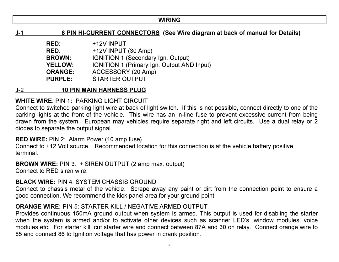
Furthermore, the system is designed for easy installation and is compatible with most vehicles. Its compact design means it can be discreetly integrated into a variety of car models without compromising aesthetics. The reliability and durability of the components ensure that the system will maintain its effectiveness over time.
In summary, the Crimestopper Security Products CS-9704 is an exceptional vehicle security system that combines innovative technology, user-friendly features, and customizable options to deliver comprehensive protection for vehicle owners. Its two-way communication, advanced sensor technology, and convenient remote start capabilities make it a top choice in automotive security solutions.
