TN-4003, TN-4004 specifications
Crimestopper Security Products has established a formidable reputation in the field of vehicle security systems, and their TN-4003 and TN-4004 models are perfect examples of this commitment to innovative technology and high-quality performance. These systems are designed to enhance the security of your vehicle, offering peace of mind and protection against theft and vandalism.The TN-4003 is a technologically advanced vehicle security system that features a two-way remote control, providing users with real-time feedback on their vehicle's status. It allows you to arm and disarm your security system from a distance, and the LCD screen on the remote displays critical information, such as if the alarm has been triggered. This feature provides an added layer of security, enabling quick responses in critical situations. The system includes a built-in shock sensor that detects any unauthorized entry or impact, instantly alerting the owner with a loud siren. Additionally, it is equipped with a range of adjustable sensitivity settings, allowing users to configure the system according to their environment.
Similarly, the TN-4004 offers enhanced capabilities with its 1-way remote system and similar features to its counterpart. It includes an array of advanced technologies such as automatic rearming, ensuring that your vehicle remains protected even if you forget to activate the system after entry. This model also features a dual-zone shock sensor, which distinguishes between light and heavy impacts, providing tailored responses based on the severity of the incident.
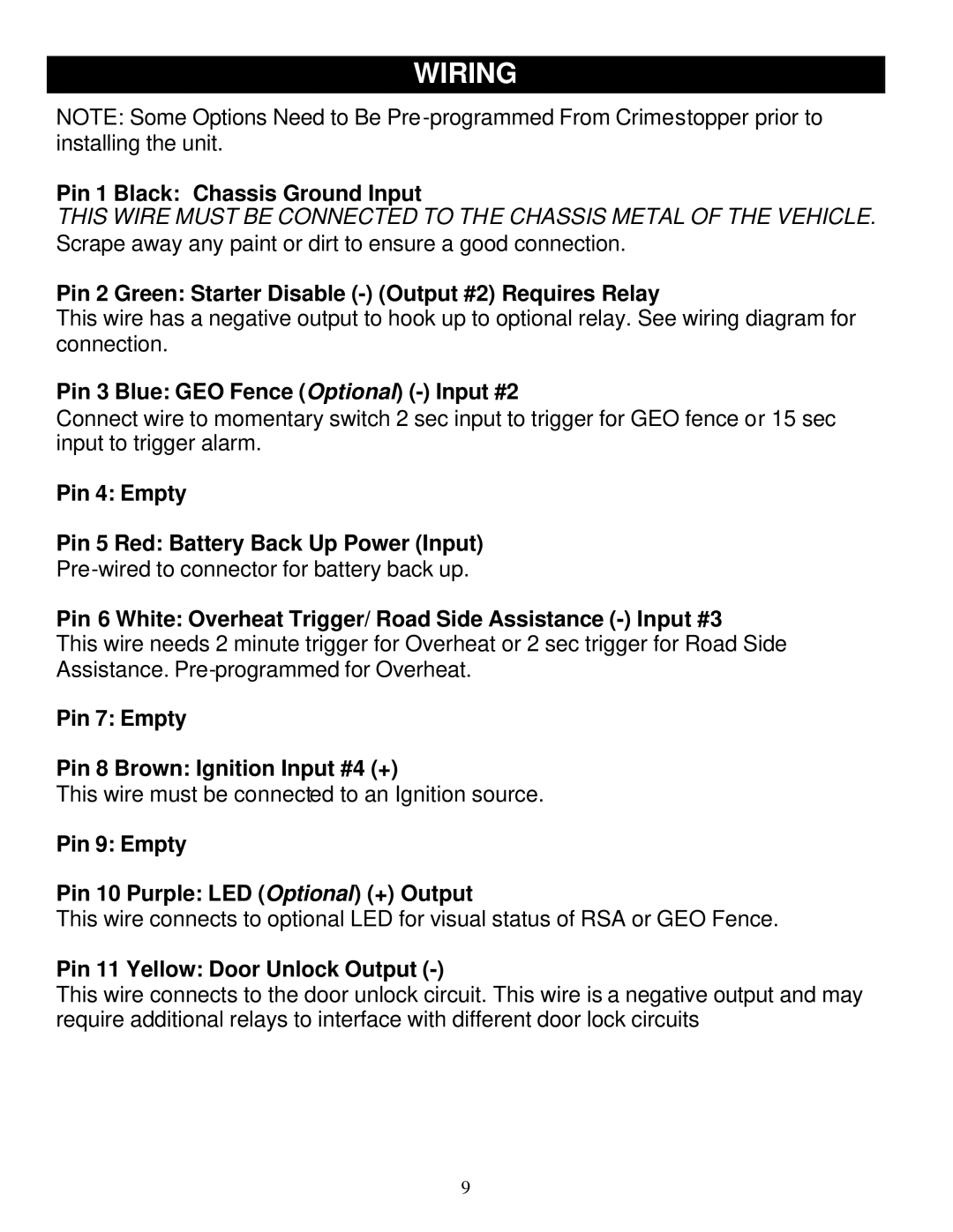
Both models boast easy installation processes, making them appealing to both professional installers and DIY enthusiasts. With a compact design, they can seamlessly integrate into various vehicle types without compromising aesthetics. The systems also come with a comprehensive installation guide to simplify the process further.
Built with durability in mind, both the TN-4003 and TN-4004 are constructed using high-quality materials to withstand environmental challenges, ensuring longevity and reliability. They are designed to operate in a wide range of temperatures, making them suitable for various climates.
In summary, Crimestopper's TN-4003 and TN-4004 models represent cutting-edge vehicle security solutions, offering robust protection features like shock sensors, two-way communication, and adjustable settings. Their user-friendly installation process and durable design make them ideal choices for drivers seeking peace of mind in safeguarding their vehicles.
