Minimum clearances on above, behind, and sides of the unit, as shown below, are required.
Those required minimum clearances are set forth in the picture below. Please keep the following instructions in mind when installing in a closet or recessed area:
•Consider allowing additional clearance for installation and servicing.
•Wall, door and floor molding may necessitate additional clearances.
•Additional inches of clearance are recommended to reduce noise while operating.
•Consider the space needed for companion appliances.
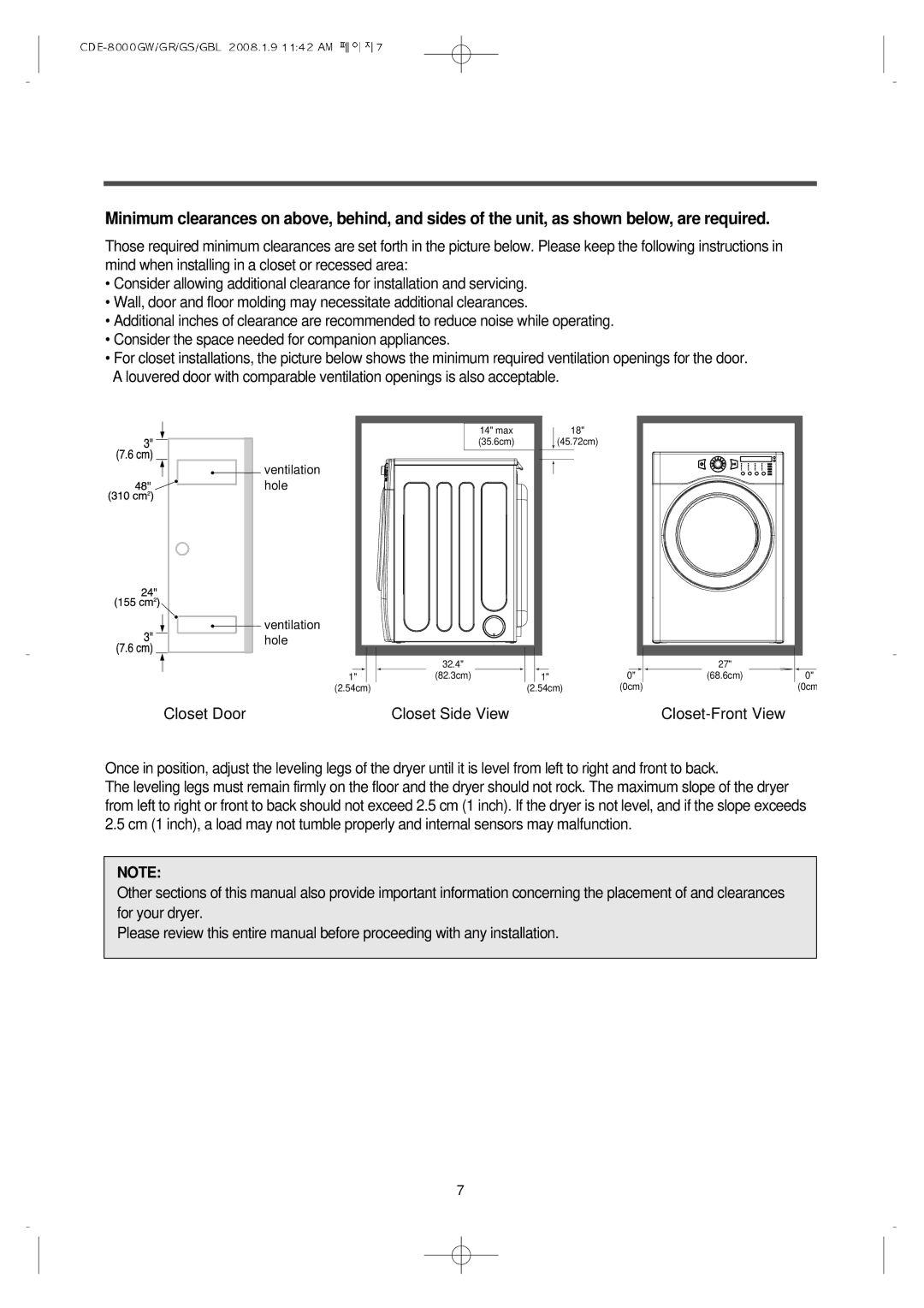
•For closet installations, the picture below shows the minimum required ventilation openings for the door. A louvered door with comparable ventilation openings is also acceptable.
14" max (35.6cm)
![]() ventilation hole
ventilation hole
![]() ventilation hole
ventilation hole
18"
(45.72cm)
1"
(2.54cm)
Closet Door
32.4"
(82.3cm)
Closet Side View
1"0"
(2.54cm)(0cm)
27"
(68.6cm)
Closet-Front View
0"
(0cm
Once in position, adjust the leveling legs of the dryer until it is level from left to right and front to back.
The leveling legs must remain firmly on the floor and the dryer should not rock. The maximum slope of the dryer from left to right or front to back should not exceed 2.5 cm (1 inch). If the dryer is not level, and if the slope exceeds 2.5 cm (1 inch), a load may not tumble properly and internal sensors may malfunction.
NOTE:
Other sections of this manual also provide important information concerning the placement of and clearances for your dryer.
Please review this entire manual before proceeding with any installation.
7